Several books and scores of articles published over the past seventy years have explored the stylistic development and regional characteristics of the American Windsor chair, but few scholars have considered how the construction of this seating changed over time. Using analytical methods derived from physics and engineering, this article documents stages in the evolution of the sack-back Windsor armchair and its most salient structural and stylistic features: the arm rail, arm supports, hoop, seat, and undercarriage. Engineering concepts and equations are accompanied by explanatory paragraphs, so nontechnical readers may skip the indented sections and still understand the results. As the following arguments reveal, form in Windsor seating followed both function and failure.[1]
Anyone who has shopped for chairs knows that many factors influence the decision to buy. Cost is a major consideration, as are comfort, stylishness, durability, and fitness for intended use. Windsor chair purchasers in the eighteenth and nineteenth centuries probably used the same criteria. Then as now the importance given to each of these concerns depended on priority, purpose, and pocketbook. A chair intended principally for outdoor use may not have functioned well at the kitchen table, and a chair suitable for a meetinghouse or a tavern may have been inappropriate for a formal parlor.
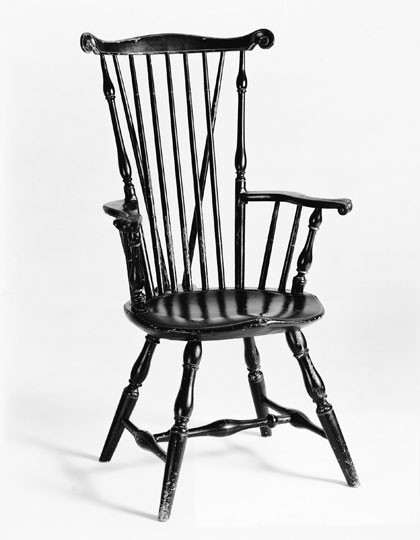
Furniture historians Nancy Goyne Evans and Charles Santore have noted that early Windsors were well suited for use in gardens because they did not obscure the view or block summer drafts, but neither scholar considered how weight may have influenced choice in chairs intended for outdoor use. Early comb-back armchairs, which often weigh at least twenty pounds, are considerably more difficult to move than lighter sack-back armchairs. Obviously, portability was less of a concern in wealthy households, which typically had servants or slaves available for the task, but logic suggests that Windsor purchasers considered size and weight when buying chairs for indoor use. Large comb-back and low-back chairs were extremely comfortable and represented a less expensive alternative to similarly commodious late baroque and rococo seating forms. The same chairs, however, were poorly suited for use around tavern tables or in rows at meetinghouses. Data compiled from chairs illustrated in Santore’s The Windsor Style in America, 1730–1830 indicates that the seat width of Philadelphia comb-back Windsor chairs decreased over time and that weight decreased as a result (see table 1). If his dating is correct, most Windsor chair seats assumed a standard width of approximately 21 1/2 inches between 1765 and 1780. Most later chairs have oval seats instead of D-shaped ones, which provided a further reduction in weight.[2]
For some individuals who purchased Windsor chairs, style and comfort were more important considerations than size and weight. This may have been especially true of furniture intended for use in formal settings, like the four Windsor chairs listed in the dining room in Philadelphia banker Charles Norris’s 1766 inventory. Judging from room-by-room inventories taken before the Revolution, Windsor furniture often stood in halls or passages, readily accessible as supplementary seating when and where need arose. The 1768 inventory of Norfolk, Virginia, merchant Robert Tucker, for example, lists ten “Windsor chairs” in the passage. It would be difficult to imagine a period context in which the architectonic turnings, carved elements, and paint colors of most early Windsors would have seemed out of place. Indeed, many of the later comb-back chairs illustrated and discussed by Santore have carved arm knuckles similar to those on formal seating (see table 1)[3]
For tavern and meetinghouse owners, strength and durability were probably more important than style in the selection of Windsor furniture because seating in those places was subjected to more frequent and rougher use. Given the fact that Philadelphia had about 20,000 inhabitants in 1760, it is likely that proprietors of many public establishments knew one another. During the course of business discussions, they probably learned whose chairs were holding up and whose were failing; they all understood that furniture repairs and replacement costs affected their bottom line. Since tavern and meetinghouse owners presumably placed large orders for Windsor seating, there must have been considerable competition to build chairs that were as strong and durable as they were pleasing to look at. Before the Revolution, Windsor style and structure may have been influenced as much by the needs of public use as by demand for seating suitable for domestic use. Shipping records suggest that Philadelphia makers captured a large portion of both markets, exporting thousands of Windsors annually. As early as the 1760s “Philadelphia chairs” were routinely mentioned in the advertisements of merchants from New York to Charleston.[4]
By the 1780s, however, the tone of some advertisements had changed. Makers outside Philadelphia boasted that their products were better than Philadelphia chairs. In the October 14, 1783, issue of the South Carolina Gazette and Daily Advertiser, Andrew Redmond reported that he made and sold “Philadelphia Windsor chairs . . . both armed and unarmed, as neat as any imported, and much better stuff.” Four years later Daniel Lawrence of Providence, Rhode Island, advertised that he made “all kinds of Windsor Chairs . . . in the newest and best Fashions . . . beautifully painted, after the Philadelphia mode.” Lawrence further claimed that his chairs were “warranted of good seasoned materials, so firmly put together as not to deceive the purchasers by an untimely coming to pieces.” According to Santore, “New York and New England chairs of the 1770 to 1790 period were in many ways better than those being produced in Philadelphia. Without realizing it, Philadelphia makers had been seduced by the siren song of the assembly line into producing a standardized, uninspired tapered leg on their chairs.”[5]
The problem was actually much more fundamental than Santore realized. Growing demand for Windsor furniture created tensions between style and structure that resulted in failures of several kinds. Study of these failures and how artisans responded to them shows that makers relied as much on applied physics as on hand skills and aesthetics to survive and prosper in the marketplace.
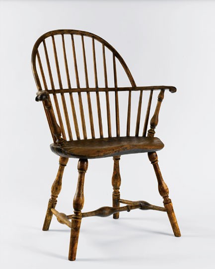
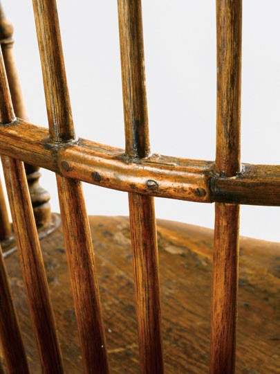
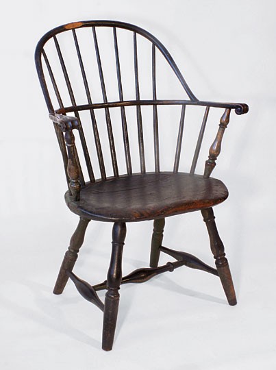
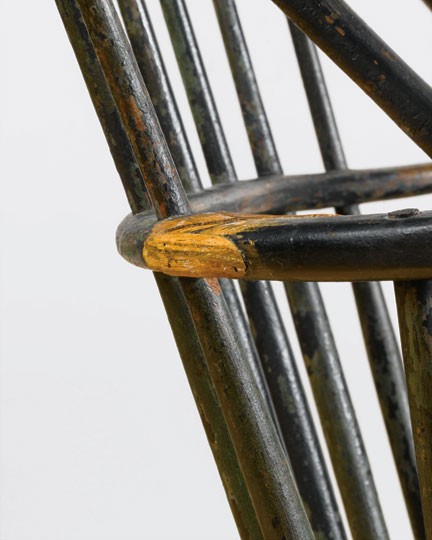
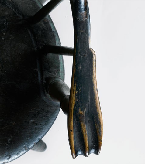
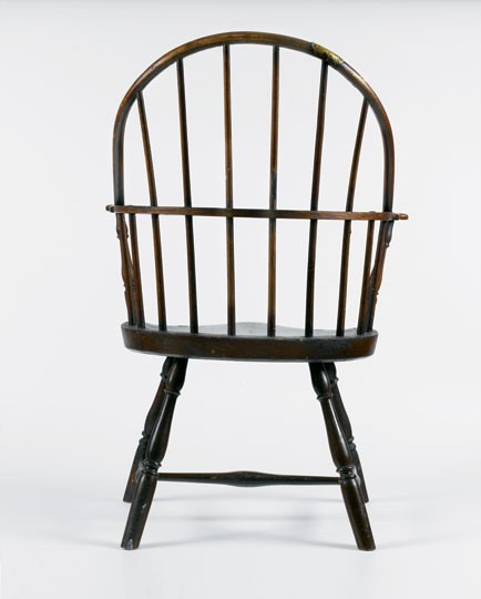
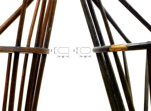
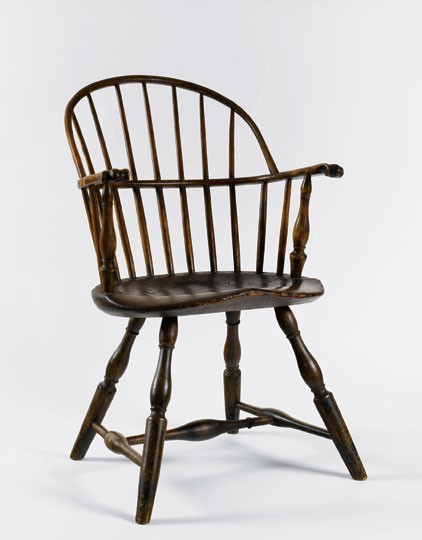
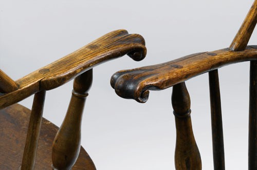
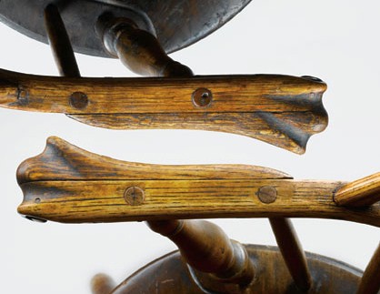
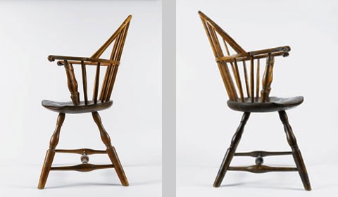
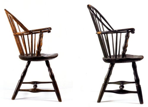
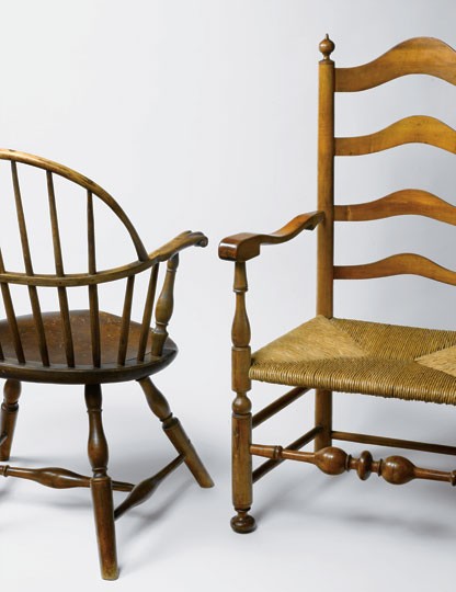
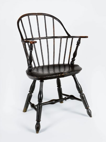
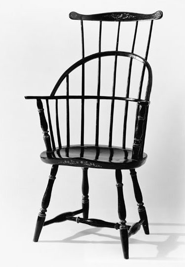
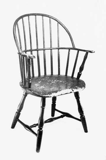
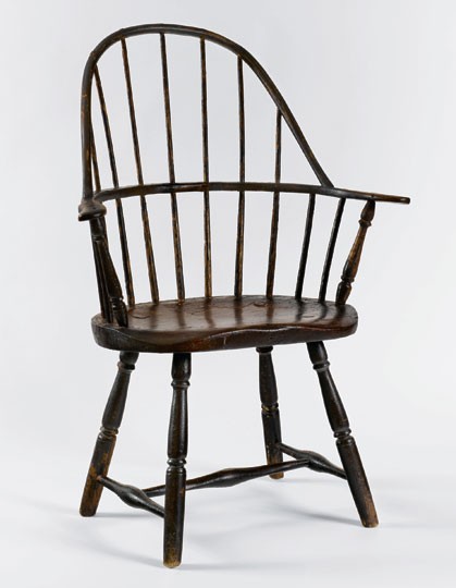
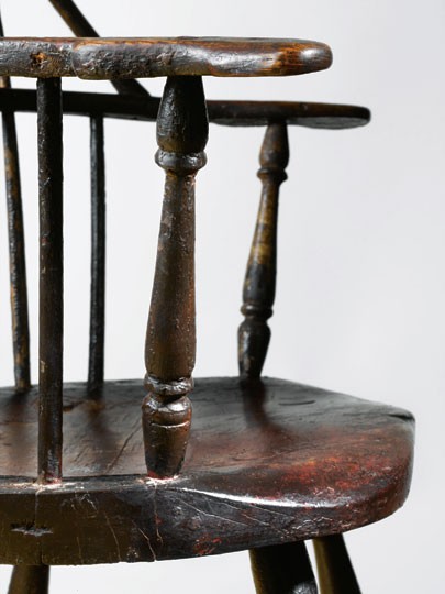
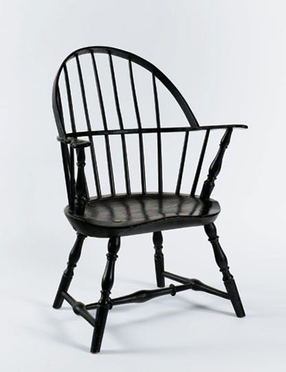
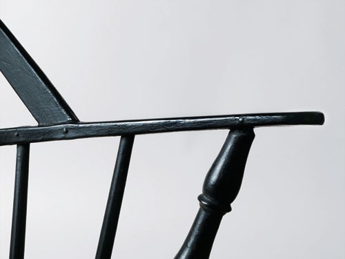
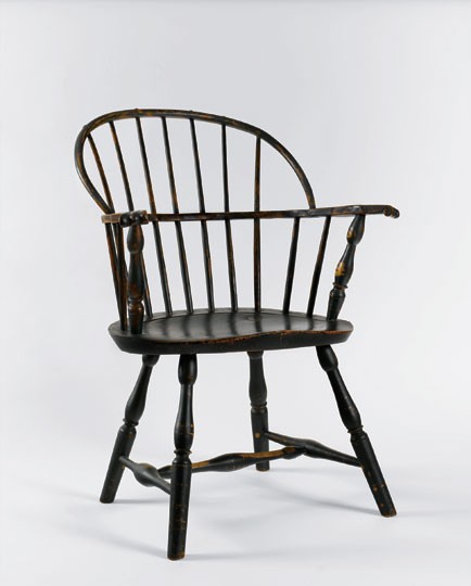
Evidence of damage to early Windors illustrates this point. The arm rail of the Philadelphia sack-back chair illustrated in figures 1–3 is repaired where it cracked at the rear (fig. 2). A similar example made by William Cox (figs. 4-7) shows evidence of a catastrophic failure, like the “untimely coming to pieces” mentioned in Daniel Lawrence’s 1787 advertisement. The arm rail on the Cox chair broke (fig. 5) and its seat cracked between the arm supports and rear legs (fig. 6). A stylish, simply turned Massachusetts Windsor (fig. 8), probably made within a few years of the Cox example, was subjected to some of the same stresses as the early Philadelphia examples, but its damage was less severe: the rear legs broke away but the arm rail did not fail. The detail illustrated in figure 9 documents a subtle but important difference between this chair and the others. The arm rails of the Philadelphia chairs are rounded at the front and back, whereas the arm rail of the Massachusetts chair is squared off at the rear. Since the “flat-back” rail of the latter chair uses more wood, common sense suggests it is stronger. Engineering failure analysis shows this as well.[6]
The Arm Rail
Children who climb trees learn basic lessons about the flexibility of wood. They discover that dry branches snap, but that green ones can be bent into U shapes or even farther. Windsor craftsmen learned early on—probably from wheelwrights—that lengths of straight-grain hickory and oak could be boiled or steamed and then bent into shapes that retained their form yet remained somewhat pliant after cooling and drying. Those who remember bending tree branches may recall that the branch always begins to break on the outside surface of the U shape, where the wood is most stretched, and that the break progresses through the branch toward the middle. Meanwhile, the inside of the U squeezes together or compresses, at least until the break is most of the way through. Like the tree branch, the outside surface of a Windsor chair arm rail is in tension, and its inside surface next to a sitter is in compression. But there is a difference. The application of steam relieves the tensile and compressive stresses created by bending. The wood fibers stretch and squeeze to accommodate these stresses. Drying and cooling “freeze” the arm in its new shape. Leaning back in a Windsor, like bending the tree branch, puts the outside surface of the U-shaped rail in tension and the inside surface in compression, while pushing out on the hand holds does the exact opposite. It compresses the outside surface of the arm and puts the inside surface in tension.
| Stress Analysis: Rounded and Flat-Back Arm Rails When a tree branch or chair rail is about to break, it has reached its maximum yield stress. Since the branch begins to break at its outside surface, one would expect tensile stress to be greatest at this surface and compressive stress to be greatest at the inside surface. Therefore, we can imagine a surface somewhere in between, where tensile and compressive stresses are neutralized. Engineers use this neutral surface to develop equations relating these stresses to material shapes and properties. The first equation below relates stress at any distance y on either side of this neutral surface to bending force B. It states what common sense suggests, that stress increases with distance y away from this neutral surface and with the size of the bending force, B.[7]
|
Charles Santore’s photographic inventory of early Windsor chairs can be used to estimate when the transition from rounded rail to the stronger flat-back rail occurred. Most of the fourteen comb-back chairs with steam-bent arms that Santore dates to 1750 or earlier appear to have arms that are rounded along their back surface, but five of the fourteen comb-backs he dates to 1750–1770 appear to have rails that are rectangular or nearly rectangular at the back. The rails of three of these five chairs are also thicker at the center rear than at the arm hold, further evidence that makers were trying to strengthen their chairs. A different situation occurs for sack-backs with steam-bent arms. Sack-backs made before 1750 are not now known, but three of the ten chairs he attributed to the 1750–1770 period have arm rails that appear to be squared off at the rear. However, none of the thirty-one Philadelphia sack-back Windsors collected for Independence Hall or made for Carpenters’ Hall during the mid-1770s have flat-back arm rails. This suggests that flat-back arm rails were uncommon in Philadelphia sack-backs, even though they occur on some earlier comb-back chairs.[9]
Chairs with Flat-Back Arm Rails
Two sack-back armchairs from the same shop (figs. 11, 12) allow an observer to distinguish the maker’s intent from later repairs. Although most Philadelphia Windsors were originally made without metal fasteners, both of these chairs have nails securing the spindles to the hoop and the arm rail. The nails at the rear of the rail were driven in from the back, but those at the sides were inserted from the inside to retard arm movement. This intelligent arrangement creates a structural web that flexes less at the arms. Both chairs have wooden pins that secure the arm supports and every other spindle to the seat, even though most Philadelphia chairs have no pins for that purpose. Many knuckle handholds were glued or nailed and have been lost over the years, but the handholds on the two sack-backs are intact. On both chairs, the maker used two small pins to secure the knuckle to the underside of the arm and two more to secure the scrolled arm extender (fig. 13). He also pinned the legs under the seat (fig. 14) and double-wedged them from above. In total the maker used seventeen pins and seventeen nails in the construction of each chair. These chairs are clearly the products of a sophisticated shop that was especially conservative from a structural point of view.
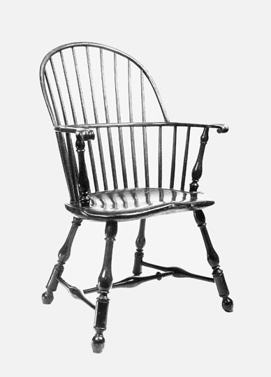
Further evidence of this shop’s sophistication can be seen in figure 15, which shows that the seat blanks of the sack-back chairs were bent before they were carved. Although most board components of period furniture have shrunk and/or bowed over time, moisture loss did not create the curvature of these seats. If it had, the side stretchers would have pulled out long ago. This bowing is also not the result of heavier jack-planing, since maximum seat thickness is about the same from front to rear. Seat bowing added a manufacturing step, but it saved wood and weight. Using this process, a maker could reduce blank thickness by one-quarter inch or more and reduce the time and effort required to shape a stylish, comfortable saddle. Few shops made bowed seats for Windsor chairs.
From a manufacturing perspective, the two sack-backs (fig. 11, 12) incorporate standardized pin and nail sizes and spindles drilled and wedged into hoops in the same way (fig. 16). Scribe lines denoting leg positions on the underside of the seats indicate that the maker used templates to lay out his holes and jigs to bore them. Philadelphia chair maker John Lambert advertised “3 Machiens for letting in feet with Propriety and Dispatch.” In the production of Windsor furniture, accurate boring is essential.[10]
As was the case with most urban enterprises, the shop that produced the two sack-backs (figs. 11, 12) employed multiple tradesmen. Two different artisans carved the arms. The knuckle edges on one of the chairs become sharp as they spiral, but those on the other chair are rounded (figs. 13, 16). In addition, the rough-carved undersides of these knuckles vary significantly.
The shop responsible for these sack-backs made at least two models, differing primarily in the rake of their rails and the angles of their seat holes (fig. 17). The rear spindles of the chair illustrated in figure 12 are more raked than those on the other Windsor (fig. 11), and the arm rail of the former is nearly twice as raked as that of the latter. Although improper repairs have changed the angles of many surviving Windsors, that was not the case with these sack-backs. Their rails have identical nails and their stretchers are parallel to the floor. The user of the chair shown in figure 11 sits rather upright while the user of the other example (fig. 12) has the option of leaning back. Both chairs could be used at a table, but the example illustrated in figure 12 is more of a lounge chair and may have been made to accommodate a close stool.
The leg splay of these structurally sophisticated sack-backs is greater than that of the Cox chair (figs. 4, 11, 12, 18) but similar to that of small, Philadelphia fan-back armchairs with rounded seats (fig. 19). In addition, both sack-backs have rearward medial stretchers like early comb-back Windsors made by Thomas Gilpin and several of his competitors. The master of the shop that produced these sack-backs was clearly familiar with a range of local options for various Windsor forms, and either he or one of his workmen was an exceptional turner. The legs on seating from his shop are considerably more robust than those on most contemporary Philadelphia examples, even though they were made from stock of the same size. Similarly, few sack-back armchairs from that city have comparable handholds (fig. 20). Finely shaped knuckles are more often found on elaborate Philadelphia comb-back Windsors with sawn arms (fig. 21). As the details illustrated in figures 13 and 16 show, the knuckles on the two sack-backs are beautifully modeled with protruding central lobes and deeply relieved volutes. In some respects, the handholds on these chairs are more vigorous than those on formal seating from the same era. [11]
Intrinsic and extrinsic evidence strongly suggests that these sophisticated sack-backs (figs. 11, 12) were made in Philadelphia during the 1760s. Their leg splay and major turnings have parallels in early fan-back Windsors from that city, and their arm supports have fat baluster elements related to those on sophisticated ladder-back chairs made in the Delaware Valley region (fig. 22). Several Lancaster examples have handholds with protruding central lobes, but no recorded chair has a flat-back arm rail like the two sack-backs. In a further departure, most Lancaster chairs have spade feet and knuckles butted to the ends of their arms. A sack-back Windsor armchair attributed to Frederick, Maryland, is one of the closest cognates to the two Philadelphia examples. The former chair has similar scribe lines and pins under the seat, related arm support turnings, and finely shaped knuckles with a prominent central lobe. Despite these parallels, the Frederick chairs appear at least one generation removed from the Philadelphia sack-backs. The more advanced structure of the metropolitan examples suggests manufacture in an intensely competitive environment where various makers were attempting to build superior chairs.[12]
More than twenty Windsor chair makers plied their trade in Philadelphia before the Revolution. Many of these artisans’ addresses are unknown, but several maintained shops in the city’s commercial district (fig. 23). William Cox worked on Second Street, Francis Trumble worked on Front and Second Streets, and David Chambers and Josiah Sherald worked nearby. The homes of many wealthy consumers were within easy walking distance. Merchant John Cadwalader and his wife Elizabeth (Lloyd) lived in an enclave of fine houses on Second Street, four blocks south of Market Street and one block from the Delaware River wharves. They purchased a dozen “round top Windsor chairs” and two settees from Trumble on July 19, 1771.[13]
If an eighteenth-century consumer crisscrossed this commercial district in search of Windsors, he or she might encounter a dozen shops offering a variety of choices. Some chair makers may have limited their production to standardized seating, while others offered a variety of options including sculpted seats, carved knuckles, and mahogany arms. A few shops may have produced chairs with different rakes that served different functions but worked well en suite (see figs. 11, 12). Just as today, artisans had to justify their prices. In the absence of documentation, one imagines the conversations and negotiations that took place as patrons and makers addressed issues of cost, strength, durability, comfort, weight, and style.
Stylistic and structural options undoubtedly varied from maker to maker depending on the size and composition of their workforce, patronage, and intended market. Trumble’s advertisements, bills, and surviving work indicate that he made several models of Windsors including examples described as “sack-back,” “arch top,” and “round top.” All were available with either “Scrol arms” or “plain” arms. Although Trumble’s reference to “Round Top Scrol arm Chairs” adequately describes the sack-backs illustrated in figures 11 and 12, his signed chairs have different leg turnings and construction details. Windsor chair makers and sellers of Trumble’s stature may have offered different levels of work—a premium grade for special commissions, a better grade for the local market, and standardized work for export. The fact that Trumble had 1,200 “Windsor chairs” on hand in 1775 suggests that he was engaged in the coastal trade. Like earlier Boston chair makers and merchant upholsterers, Trumble may have purchased piecework from independent turners and assembled chairs from parts made in other shops.[14]
Table 2 lists the names of at least a dozen Windsor furniture makers working in Philadelphia before the Revolution for whom few if any signed chairs are known. Most of these artisans can be considered potential candidates for the maker of the sack-backs illustrated in figures 11 and 12, but several factors make attributions of unlabeled or unbranded Windsor chairs to specific artisans problematic. Many Philadelphia chair makers, including Trumble, Cox, Joseph Henzey, and William Widdifield, were members of the Society of Friends. Quaker artisans typically took apprentices of the same faith and often engaged in mutually beneficial business arrangements including buying and selling piecework and collaborating to assemble furniture cargos for export. The Society of Friends also maintained a Windsor chair manufactory on Front Street in the third block north of Market Street, facing the Delaware River (see fig. 23). This enterprise and the aforementioned practices probably promoted standardization of some aspects of Philadelphia Windsor design[15]
The Rectangular Arm Rail
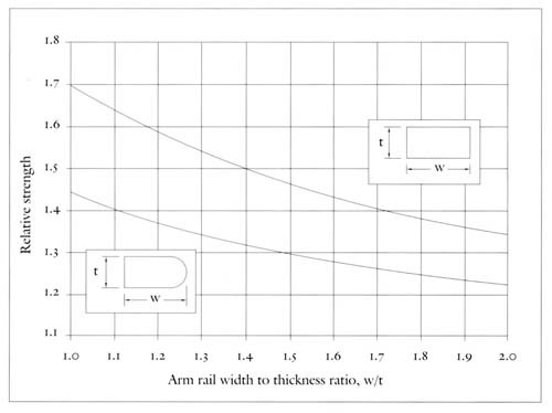
Although the flat-back rail is considerably stronger than the rounded rail, it was never common in Philadelphia. Not one of the many sack-back chairs collected by Charles Dorman for Independence Hall has flat-back arm rails. Most chairs documented and attributed to the city have rectangular or rounded rails. Since chair rails were carved and shaved from logs split along the grain, those who made them must have known that larger cross-sections were stronger. Therefore, it should come as no surprise that some Philadelphia makers used fully rectangular rails from an early date. The graph in figure 24 summarizes calculations in appendix 1 comparing rounded and flat-back rails with rectangular rails. The rounded rail with a width-to-thickness ratio ranging between 1.3 and 1.6 becomes 40–50 percent stronger if its front and rear surfaces are squared off. The rectangular rail was even stronger than the flat-back rail, and it saved labor and cost.
A small group of sack-backs at Carpenters’ Hall (fig. 25) indicates that Philadelphia chair makers were producing Windsors with rectangular rails before the Revolution. These chairs are from two sets in use when the First Continental Congress met there in September 1774. The Carpenters’ Company paid twenty shillings for the first set—described as “Chares for the Hall”—in January 1773. These Windsors were branded with dates six years later. The second set was probably purchased for the Library Company of Philadelphia, which moved from the Pennsylvania State House into space rented from the Carpenters’ Company on September 6, 1773. To furnish the Library Company’s new space, the Carpenters’ Company also acquired six brass sconces and two chandeliers. The chairs from both sets have very similar handholds and arm supports, and for years were considered a set of five, but four have 21 1/2-inch-wide seats and rectangular rails (see fig. 25) and one has a 20Q 1/4-inch-wide seat and a rounded rail.[16]
Quantitative analysis explains why the chairs with rectangular rails survive in greater number. The rectangular rails of the chairs represented by the example illustrated in figure 25 are more than 50 percent wider than the rounded rail of the smaller fifth chair. Since the strength of a rectangular rail varies with the cube of its width (see eq. 3, fig. 24), a 50-percent wider rectangular rail with the same thickness is about 3.375 times stronger (1.53 = 3.375). The rounded rail of the smaller chair has a width-to-thickness ratio of 1.5 and would have been about 1.5 times stronger had it been rectangular. Therefore, the rails of the four chairs with rectangular rails are roughly five times stronger (3.375 x 1.5) than the rail of the one chair with a rounded rail.
| Equation 3 can be used to make a more exact comparison including differences in rail thickness. The rounded rail is 0.656 inches thick and 0.993 inches wide; the rectangular rails are about 0.810 inches thick and 1.510 inches wide. |
| At some position y, |
s (y)
s2/ s1 |
=
= = = |
By/I = 12By/tw3 |
| Since the stress at any given point in the wider rectangular rail is about 23% as large as in the smaller one, it is 1/.2303, or 4.34, times stronger. On the other hand, the rounded rail with a width-to-thickness ratio of 1.51 would be 1.47 times stronger according to figure 24 if it had been rectangular. Therefore, according to this more accurate calculation, the rectangular rails on the four wider Carpenters’ Hall chairs are 4.34 x 1.47, or 6.37, times stronger than the rail on the single surviving chair with a rounded rail. |
The Philadelphia sack-back chairs examined for this study provide statistical insight into the transition from rounded to rectangular rails. Seven of twelve nine-spindle sack-backs have rounded rails, whereas the remaining five have rectangular rails (see table 3). By comparison, thirteen of twenty-three seven-spindle Philadelphia chairs have rectangular or flat-back rails; the remaining ten have rounded rails. In other words, almost 60 percent of the nine-spindle chairs have rounded rails, whereas nearly 60 percent of the seven-spindle chairs have rectangular or flat-back rails. Probability experts are cautious about drawing conclusions from limited samples, but these are not inordinately small; early field trials of experimental drugs use samples of about the same size. The Windsor samples support Evans’s assertion that sack-back chairs with seven or nine spindles were made concurrently, but they also suggest that nine-spindle production began earlier because their makers favored the rounded rail used on many nine-spindle comb-backs. The verticality of the nine-spindle sack-back chair illustrated in figure 1 is related to early comb-backs as well.[17]
Although many surviving Philadelphia sack-back Windsors have rounded or partially rounded rails, this is not the case for chairs made elsewhere. All of the early Lancaster area chairs discussed in Evans’s and Santore’s monographs appear to have rectangular rails, even though most have seats 21–21 1/2 inches wide, like many pre-Revolutionary Philadelphia examples. Rectangular rails are also common on Rhode Island Windsors, which typically have narrower seats. Of the twenty-two sack-backs measured and illustrated in Evans’s book, fifteen have rectangular rails and seats 20 1/2 inches wide or less.[18]
With regard to Windsors made in New York City, the situation is much the same. Three sack-backs Santore attributes to that city have bold turnings, rectangular rails, and seats nearly 20 1/2 inches wide. He dates these chairs between 1765 and 1780, concurrent with his dates for early Philadelphia sack-backs, but his own work on continuous-armed New York Windsors includes a New York chair with equally robust turnings marked by the firm Hampton and Always, whose short-lived partnership date is documented to 1792. There is reason to believe that these New York sack-backs were made after the Revolution and are later than most Philadelphia examples with wider seats and rounded arms.[19]
Finally, all of the armchairs with 21 1/2-inch seat widths (excluding chairs with D-shaped seats) that Evans attributes to Boston and Rhode Island have rectangular rails. Many of these chairs also have legs with greater splay than similar Philadelphia examples and wide baluster-shaped arm supports with thin, elongated tops. Therefore, it is probable that the makers of at least some of these chairs were familiar with sophisticated sack-backs similar to those illustrated in figures 11 and 12.[20]
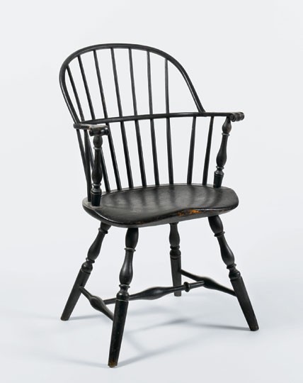
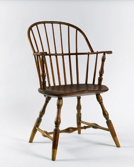
Once makers realized that cross-sectional width was much more important to arm rail strength than vertical thickness, arm rails became sleeker in side section and turnings became thinner, especially in New England. The Windsor illustrated in figure 26 is strong enough for daily use, even though it is light and has few of the nails and none of the pins found on some earlier products. Several American artists depicted men and women seated on similar chairs more than a hundred years after their manufacture, a testament to the durability and strength of this seating form (fig. 27).
The Locking Arm
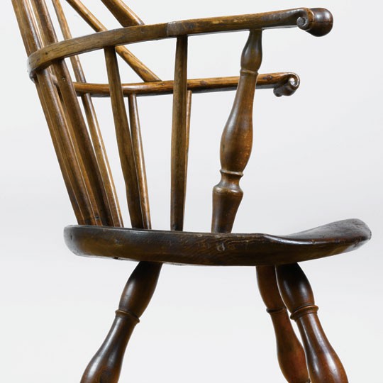
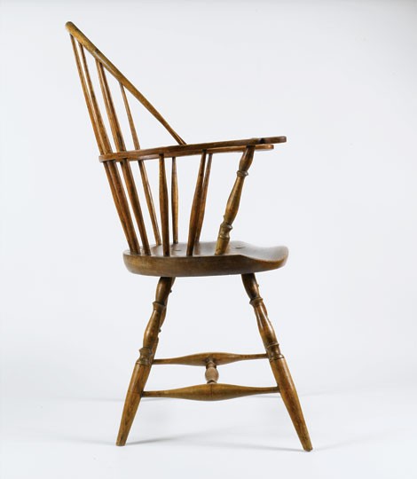
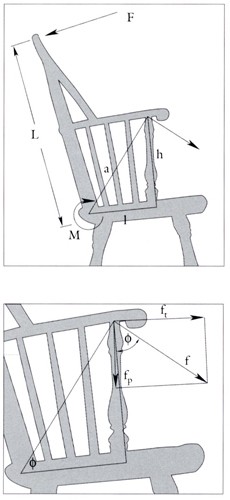
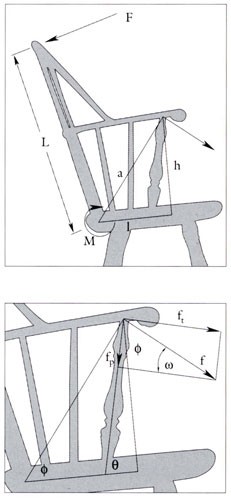
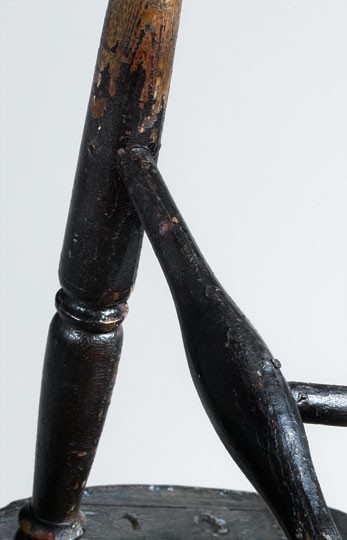
Although changes in arm rail strength have been the focus of this article so far, other structural developments occurred as Windsor chair makers sought to prevent an “untimely coming to pieces.” The arm support played an important role as the chair evolved from a design with strength based on rigidity toward a design with planned flexibility. The chair illustrated in figure 1 has arm supports that are nearly perpendicular to the seat when seen from the side, like the arm supports on many tall-back and low-back armchairs (fig. 28). By contrast, the chair shown in figure 4 has forward-canted arm supports and hoop anchors placed far forward. Neither Windsor has pins or nails at the tops or bottoms of its short spindles or arm supports, but the arm supports of the chair illustrated in figure 4 are strengthened with handmade metal tensioning bars. When a sitter leans back in such chairs, the hoop and back spindles bend back slightly. Since the hoop is anchored at the rail, the rail is also pulled; the more forward the hoop anchor, the more direct the pull. If the arm supports and short spindles are nearly perpendicular to the seat and not pinned or nailed at the arms, there is nothing save the tightness of the wedged arm supports and short spindles to keep the arms from pulling away and failing. The arm supports of these chairs did pull out at one time. This probably explains why few early sack-backs with nearly vertical arm supports have survived.
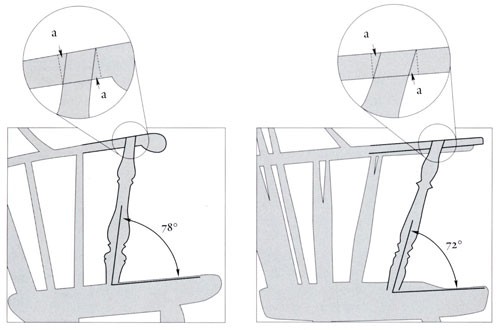
To fix this problem, a few Philadelphia chair makers pinned or nailed their arm supports and short spindles, but most craftsmen decided instead to cant the arm support about 10 or 15 degrees forward (fig. 29) and to limit the side splay of the arm (see figs. 1, 4). The forward-canted arm support was a structural advancement because it placed the arm support rail joints in tension created by leaning back on the chair. In other words, forward canting produced an arm lock that became stronger when the chair was sat on. With the arm supports canted to the sides (see fig. 1), the locks are still present, but pushing the arm rail to the side when a sitter rises partially circumvents them and may damage the chair.
| Moment Analysis and Arm Support Pullout An engineering moment balance addresses these points and others. In this analysis, forces act at various distances from a point of rotation, called a fulcrum or a hinge. Two forces of the same magnitude equidistant from the hinge, acting on opposite sides and in opposing directions, balance, just like two children of the same weight sitting equally distant from the balance point on a seesaw. A smaller force farther away from the fulcrum can balance a bigger force, like a smaller child sitting farther out on the seesaw, but a third child sitting on the balance point has no effect, no matter how much that child weighs. When a person leans back on any armchair, forces are created along the back of the chair (see figs. 28, 29). The force distribution depends on sitter height and posture, but since the force most distant from the seat is potentially most destructive, the situation can be simplified using a single resultant force F acting at the top of the hoop at distance L from the fulcrum; the greater the lean back, the greater the force. This force creates a moment M at the base of the back of the chair, but the back of the chair resists this moment; the more rigid the spindles and the greater their number, the greater the countermoment. Net rearward bending force Fn is less than the applied force F created by leaning back because of the resistance to bending offered by the rear of the chair.
The force f acting at the top of the arm supports can be resolved into two components, one acting along the arm supports to pull them out (fp), and a second acting along the arms to pull them back. If the arm supports have little or no forward cant (see fig. 28), the force fp acting to pull them out becomes
Equation 6 can be used to compare the size of the pullout force for various arm support cants. Since ϕ is about 45° for most sack-backs, the pullout force with a 10° forward cant is approximately sin 35°/ sin 45°, or 81% of the pullout force for an arm support without canting. With a 20° forward cant, the pullout force is about sin 25°/ sin 45°, or 60% of the pullout force without canting. With a 20° forward cant, the force acting to pull out the arm support is almost halved. As the diagrams in figures 28 and 29 show, the greater the forward cant the greater the force pulling back on the arm rail to keep it locked in place. These equations are simplifications. The lean-back force should be evenly distributed in some reasonable way, and the short side spindles under the arm should be included. But little can be gained by doing so at this time because the resulting equations cannot be solved. There is no quantitative information regarding the relative strength of joints with single and double wedges. One can only surmise that joint strength depends on the number of wedges, on wedge angle relative to the grain, and on joint contact area. |
Arm Lock Development
The analysis above shows that the arm support with greater forward cant is stronger. With a 10-degree cant, the pullout force generated at the top of the arm support by leaning back is reduced by about 20 percent. With a 20-degree cant, the force is almost halved. Arm lock strength is also affected by the thickness of the arm rail where the support is tenoned in place. The 12-degree lock on the Philadelphia chair illustrated in figure 4 is no more susceptible to pullout failure than the 18-degree lock on the armchair shown in figure 26 because the former chair has a thicker rail (fig. 30). Most Philadelphia makers used a thicker rail and a less canted support to address the pullout problem.
The thirty-five sack-backs sampled to determine when and how the transition from rounded to rectangular rails occurred provide insights into how Philadelphia chair makers laid out their arm supports. In the case of arm rails, either makers used rectangular ones or they did not, but with arm supports the situation was different; forward cants range from almost nil to nearly 20 degrees. However, patterns do emerge. Several of the nine-spindle chairs with rounded rails in this sample have arm supports canted less than 5 degrees, and none has supports canted more than 10 degrees. One of the seven-spindle chairs with rounded rails has supports with a slight cant, but most have supports canted 10 degrees or more. On the other hand, half of the seven-spindle chairs with rectangular rails have supports canted nearly 10 degrees, while the others have supports canted 15 degrees or more.
The chairs in this sample document a chronological transition from nine-spindle chairs with rounded rails and near-vertical arm supports to seven-spindle chairs with stronger rectangular rails and 15-degree arm supports, but variations along the way suggest that other influences were at work. Some early Philadelphia chairs with blunt arrow feet have strongly canted arm supports (fig. 31), as do Windsors from both sets made for Carpenters’ Hall (see fig. 25). In contrast, a few late eighteenth-century chair makers including Lewis Bender and Thomas Blackford, who moved from Philadelphia to Boston in the mid-1780s, used supports with little cant (figs. 32, 33). A chair made by Bender in the mid-1790s also has a rounded rail. All of the Joseph Henzey chairs in this sample have near-vertical arm supports (fig. 34 andtable 3), but this structural shortcoming apparently had little effect on the appeal of his products. He had a very successful career.[21]
The Hoop
Three factors have been discussed in relation to arm support pullout failures in early Windsors: arm support cant angle, arm thickness at the arm support, and arm rail width. In summary, the smaller the arm support forward cant, the smaller the horizontal tension on the arm support and the greater the risk that leaning back and pulling on the arm will pull it away from the chair. But for any arm support cant, thicker arms provide greater physical barriers to arm support pullout, and wider arms reduce the flex that could allow these physical barriers to be overcome. There is a fourth factor for chairs without pins or nails at the tops of their arm supports: the taller the hoop or bow, the greater the risk that leaning back will generate a force sufficient to pull the arms away from their supports.
| Back Height and Arm Pullout A moment balance is used to develop this height relationship. If equations 4 and 5 are combined, pullout force fp is related to lean-back force F for any arm support forward cant θ, hoop height L, and spindle stiffiness M.
|
Since l and h are relatively fixed for most armchairs (see figs. 28, 29), and since ϕ is tan-1(h/l), fp is a direct function of hoop height L for any spindle stiffness M and arm support forward cant θ. Therefore, for any sack-back chair, this equation provides the result that would be expected intuitively: the taller the hoop, the greater the pullout force on the arm supports and the greater the risk of arm support pullout failure.
The makers of sack-back Windsors had three ways to reduce the risk of arm support pullout caused by tall hoops. They could pin or nail the arm supports, top and bottom; they could thicken the arms to increase the size of the locking lip (see fig. 30); or they could keep hoop height low. The sack-back armchairs with flat-back rails illustrated in figures 11 and 12 have wrought sprigs at the tops of their arm supports and short spindles, and pins at the bases of two of their four short spindles and their arm supports. Chairs like these were uncommon, however; only two of the Philadelphia-area examples in this study have pins or nails securing the tops of their arm supports (figs. 35, 36). The earlier chair (fig. 35) has a shallower seat than the Windsor shown in figure 1 and unusually bold baluster turnings. The later example (fig. 36) bears the brand of Anthony Steel, who did not begin work until 1790 or 1791. With regard to arm rail thickness, tables 3 and 4 show that it did not change much; the average for twelve nine-spindle chairs is .731 inches, while the average for twenty-three seven-spindle chairs is .723 inches. Most Philadelphia makers chose instead to keep hoop heights relatively low.
Chair makers who did use pins or nails to secure their arm supports could create tall sack-backs with pullout-resistant rails. A chair found in Easton, Pennsylvania (figs. 37-39), has a very tall hoop, wide arm splay, and a very shallow seat. Evans and Santore illustrate other tall-back Windsors from Lancaster, Pennsylvania, and New England. Since the hoops of these tall chairs are about 40 percent higher than most and their spindles are about average in diameter, equation 7 shows that leaning back on one of them creates much more pullout force at the arm support than would usually be expected. Since most Philadelphia sack-backs lack pegged or nailed arm supports, it is not surprising that no tall-back example is known. Evans suggests that tall-back chairs were made for invalids and the elderly who would not subject them to heavy use.[22]
Equation 7 is not completely valid for comb-back armchairs because there is no direct link between the tall spindles at the rear and the arm supports. But there is an indirect link; the more rigid and plentiful the tall spindles, the more direct the pull on the arm at the arm support when a sitter leans back on the chair. Therefore, early comb-back Windsors probably suffered from the same arm support pullout problems. Evidence supports this. Seven of the nine comb-back armchairs at Independence Hall are pinned at the tops of their arm supports. Most of those chairs have pins at the tops of some short spindles as well.[23]
Hoop Spindle Penetration Cracks
Most hoop failures are cracks where the spindles penetrate the hoop and reduce its cross section by 40 percent or more. Such cracks typically occur at the rear of the spindle because the rear of the hoop, like the rear of the arm rail, is in tension when a user leans back. Although hoop cracks are not catastrophic failures like arm support pullouts or seat breaks, they weaken the superstructure and make the chair unsatisfactory for public display and use.
Physical evidence suggests that many Philadelphia chair makers believed the fewer the spindle penetrations, the smaller the risk of hoop failure, because the hoop then remains more whole. Some early Windsors, like the one illustrated in figure 31, have only five spindles, whereas others have only one or two spindles penetrating the hoop. Most Philadelphia makers used four penetrating spindles. With seven-spindle chairs, the penetrations are typically at the 2, 3, 5, and 6 positions, and with nine-spindle chairs they are typically at the 2, 3, 7, and 8 positions. The end spindles rarely penetrate the hoop. Most makers drove a wedge into the end of each penetrating spindle perpendicular to the grain, but some used wedges set parallel to the grain or on the bias, and others peened the ends of the spindles. The following chart illustrates common penetration patterns for nine- and seven-spindle chairs. Symbols used here are repeated in tables 3 and 4.
| Philadelphia nine-spindle hoops |
1
|
2
|
3
|
4
|
5
|
6
|
7
|
8
|
9
|
| Wedges parallel to the grain |
|
Ө
|
Ө
|
|
|
|
Ө
|
Ө
|
|
| Wedges perpendicular to the grain |
ϕ
|
ϕ
|
|
|
|
|
ϕ
|
ϕ
|
|
| With a small central penetration |
ϕ
|
ϕ
|
|
|
o
|
|
ϕ
|
ϕ
|
|
| Peened, not wedged |
O
|
O
|
|
|
|
|
O
|
O
|
|
|
|
|
|
|
|
|
|
|
|
|
| Philadelphia seven-spindle hoops |
|
1
|
2
|
3
|
4
|
5
|
6
|
7
|
|
| Wedges perpendicular to the grain |
|
|
ϕ
|
ϕ
|
|
ϕ
|
ϕ
|
|
|
| With a central penetration and a crack |
|
|
ϕ
|
ϕc
|
O
|
ϕ
|
ϕ
|
|
|
Concerns over diminished hoop integrity may explain why some Philadelphia chair makers used nails to reinforce their spindle penetrations. The strong seven-spindle sack-backs with flat-back arm rails shown in figures 11 and 12 have five penetrations—three in the middle and one at each end—rather than four as do most Philadelphia examples. For added strength, the maker of those sack-backs wedged the spindles on the bias and secured them with small wrought sprigs nailed in from the rear. A few Philadelphia chairs with seven spindle penetrations and no nails are also known.
The hoop-spindle attachments for all of the Philadelphia sack-backs in this study are shown in tables 3 and 4. Most of the nine-spindle chairs have spindles that penetrate the hoop at the 2, 3, 7, and 8 positions and are secured by wedges driven in perpendicular to the grain. All of Joseph Henzey’s nine-spindle chairs have penetrating spindles at the 2, 3, 7, and 8 positions, whereas two of Francis Trumble’s three chairs have six or seven penetrating spindles. Most of the seven-spindle sack-backs also have four spindle penetrations, but there are exceptions. Several have five penetrations securing the ends of the hoop like the flat-back armchairs or across the middle, five in a row, whereas two of the chairs have seven penetrations. Other variations can be observed in the Windsors made for Carpenters’ Hall. The chairs from the set with strong, wide rectangular rails (see fig. 25) have only four hoop penetrations, whereas the single example with a much weaker rounded rail has five hoop penetrations like the stronger chairs with flat-back arm rails.
Rather than indicating whether some chairs are weaker or stronger than others, the data in tables 3 and 4 reveals fundamental, even philosophical, differences among Philadelphia makers regarding how best to secure the hoops of their sack-back chairs. Surviving Windsors with cracked hoops provide some insight (fig. 40). Three of the four Philadelphia chairs in this study with four spindle penetrations and rounded rails have one or more hoop cracks, whereas none of the chairs with seven spindle penetrations made in Philadelphia or elsewhere has cracked hoops.[24]
Engineering analysis suggests why hoop cracks are less common with seven hoop penetrations and rectangular rails, provided that the hoop diameter is not undersized. Calculating the stresses on a given system of hoop spindle joints for a given sitter is beyond the scope of this article and falls within the purview of mechanical engineering finite element analysis. Nevertheless, one can develop a mental picture of these stresses based on geometry and an understanding of structural properties.[25]
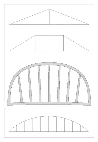
When a hoop cracks at a spindle penetration, the wood has been subjected to a local stress greater than it can bear. If, as is often the case, the hoop has a constant diameter along its length where the spindles intersect, this failure-inducing stress is not the result of reduced hoop cross-section; the cross sections are all about the same. What remains for consideration are bending stresses that occur when a sitter leans back or flexes the chair arms—the same stresses discussed earlier in reference to tree branches bending until they break. If the hoop is penetrated and wedged at all positions, bending stress is evenly distributed and not localized at any one spindle. If the hoop is penetrated and wedged at only four positions, however, stress may be localized at some point or points along the hoop, and failure may occur.
Contrary to common sense, a hoop with fewer spindle penetrations is weaker. With more penetrations, the arm and the hoop above it are more locked together, and they move as a unit when the chair is sat on. This structure has engineering antecedents in the king and queen post trusses found in medieval and later buildings and cognates in modern suspension bridge design (fig. 41).
Solving the Hoop Crack Problem
Flexing the arms of a sack-back from side to side also produces a focused flex in a hoop not fully penetrated by spindles. When the arms move sideways, the ends of the hoop move with them, and the hoop must flex to accommodate this movement; the more forward the ends of the hoop, the greater the flex. If the spindles penetrate the hoop at the 2, 3, 5, and 6 or the 2, 3, 7, and 8 positions, bending stress will probably concentrate near the middle of the hoop because the ends of the hoop are in sitting tension and the spindles in between are fairly well tied down. Therefore, the working relationship is that the weaker the arm rail, the greater the arm flexibility and the greater the hoop movement. This probably explains why surviving chairs with stronger rectangular rails have fewer cracked hoops.
Since hoops are made of green wood, they are pliant and supple at first. Over time, the wood dries out and becomes susceptible to cracking. The rate at which this happens depends on how well the hoop is protected by paint or varnish and where the chair is used. The hoop of a sack-back with four penetrations (see fig. 4) did not crack until recently, but there is evidence that eighteenth-century Philadelphia makers knew that hoops were prone to cracking and sought ways to remedy the problem. Some chair makers, including Francis Trumble and Ephraim Evans, made sack-back Windsors with seven penetrating spindles, whereas Anthony Steel used five fully penetrating spindles across the back in a row (see tables 4). Evans worked in Philadelphia between 1779 and 1785, while Steel’s career lasted from about 1790 until his death in 1817, but Trumble began work in about 1760 and made chairs for forty years. Therefore, Trumble’s chairs may document a transition from few hoop penetrations to many penetrations over the course of his career (see tables 3, 4 ). In contrast, most New England sack-backs have only penetrating spindles (see table 5), as do many comparable Windsors made in the southwest of England.[26]
Use of seven or nine penetrating spindles was not the only way to reduce the risk of hoop cracking. An early New England armchair with an outsize rectangular-sectioned hoop (fig. 42) was probably made in response to this problem. The hoop is about 1.125 inches wide and one-quarter inch thick, and it looks as though someone trained as a wheelwright made it. Since the penetrating spindles remove a small percentage of its cross section, the risk of cracking is greatly reduced. The detail illustrated in figure 43 shows that the hoop is original to the chair. Its locking pin is the same size and shape as the pin holding the arm support, and the paint layers in both areas are undisturbed. Few American chair makers used rectangular hoops, but some makers used hoops that were thicker near the center for additional strengthening. Other makers tapered the hoop near the arm rails so it would flex near the ends instead of at the spindles, where so much wood had been drilled away (fig. 44). The chair illustrated in figure 26 has both features; the example shown in figure 44 has a hoop that tapers and turns near the arm rail terminations, creating an extra length of hoop that keeps bending stresses away from the relatively weak hoop-spindle penetrations. Tapering of the hoop near the arm rail may have been a structural advance when the chairs were made, but it created cracking problems near the arm rail if the wood dried out and became brittle over time.
The Seat and Undercarriage
Most eighteenth-century Windsor chair seats are thick boards pierced by legs with one or two wedges to keep them snug. Some seats are blind-socketed, especially those on Rhode Island and eastern Connecticut chairs. Blind-socketed seats are aesthetically pleasing because the upper surface is unmarred by construction details; they are strong because they are usually made of a hard wood like maple, and the legs are often pinned through the rear or sides of the seat. By contrast, through-socketed seats are easier to make and more receptive to adjustments in leg splay during manufacture, especially when softer woods are used. Through-socketed seats are also self-locking. When a chair with through-socketed legs is in use, sitting weight pushes down on the seat around the legs and tightens it against the sides of the pierced leg joints. Today, the legs of some early chairs protrude one-eighth of an inch or more. This self-locking capability is analogous to the self-locking arm created by the forward-canted arm support discussed above.[27]
Although one might expect thick one-board seats to be strong, seat cracks and breaks are common in early Windsors. As the chairs illustrated in figures 1 and 4 suggest, this type of damage is usually found at the arm supports or between the rear legs (see figs. 3, 6). Since the seats of most early armchairs are more than twenty-one inches wide, cost-conscious chair makers had no choice but to orient the wood grain from side to side if they wanted to avoid the added effort of wood matching and gluing. Most Philadelphia makers chose tulip poplar for their seats, whereas most New England makers chose white pine. Tulip poplar is relatively dense; early sack-back Windsors with seats made of that wood typically weigh about fifteen pounds. With white pine seats, chair weight could be reduced about 10 percent, but that wood’s lower density made the seat weaker and more susceptible to cracking. Philadelphia makers rarely, if ever, used elm, which is common in English Windsor seats. This comes as no surprise, given their access to less brittle and more easily worked woods.
Post Thickness and Seat Failure
A pry bar analogy helps to explain why Windsor chair seats crack at the arm supports. Since Philadelphia arm supports are relatively thick and therefore rigid, sitting forces that pull back on the arm rail are directly transmitted into the seat at the bottom of the arm support. With early chairs like the one shown in figure 1, the arm support is wide where it enters the seat, but with later chairs (see fig. 4), the support is smaller.
| 1 | 2 | 3 | 4 | 5 | 6 | 7 | |||
| n | n | n | n | n | |||||
| Ø | Ø | Ø | Ø | Ø |
From an engineering perspective, figure 29 shows that the horizontal prying force created by leaning back is greater when the arm support is more canted:
The greater the forward cant of the arm support, the smaller the value of θ and the greater the value of f cos (θ − 45°), the force acting on the pry bar. This and the use of pine for the seat help to explain why the seat of the Cox chair (figs. 4–7) cracked at its arm supports. |
Some Windsor chair makers found ways to reduce or eliminate damage from pry bar forces that did not compromise the arm lock created by forward canting. The arm supports of the Philadelphia chair illustrated in figure 33 have relatively thin lower sections that reduce the risk of pry bar failure because seat holes are smaller; the pry bar force is the same, no matter what the diameter of the rigid arm support, but the seat is stronger because less of it is taken away. Likewise, the seemingly underdeveloped supports of the New England chair shown in figure 26 are even more structurally advanced because they are thinner throughout their length. The arm support flexes with the spindles as one sits back instead of transmitting pry bar forces directly into the seat of the chair.
The pry bar analogy also holds for Windsor chair legs. Thicker legs need wider seat holes; the thicker the leg joint, the greater the risk that the seat will crack if a side stretcher fails when a sitter leans back on the chair. Therefore, thinner legs, like those of the chair illustrated in figure 26, were also a structural step forward, provided that seat thickness remained comparable and that reduction in leg thickness did not cause other structural problems. Intuition suggests that the greater the leg splay, the greater the force the stretcher joints must bear if the chair is to remain intact. Engineering failure analysis confirms this and demonstrates that the chair with stretchers higher off the floor may be the weaker chair.
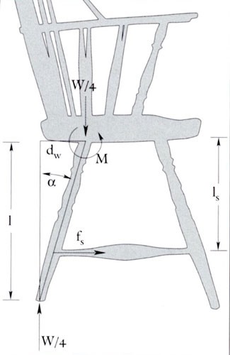
| Leg Splay and Stretcher Failure If a sitter’s weight W is evenly distributed on a Windsor chair seat, each leg bears W/4, provided that the chair sits flat on the floor. A moment balance at the point where a leg enters the seat relates this weight to the tensile force fs pulling on the side stretcher below it (fig. 45). The balance is written around this point because the leg would start to hinge around it and pry on the seat if the stretcher let go. Since the chair does not move when it is on a level floor, the only other force to consider is provided by Sir Isaac Newton’s First Law of Motion: for every action there is an equal and opposite reaction. The weight pushing down on each leg is balanced by a reaction force of equal magnitude pushing up from the floor. With reference to figure 45,
|
Leg splay changed as the American Windsor developed (fig. 46). On the early Philadelphia sack-back chairs illustrated in figures 1 and 4, the front legs splay about 14 degrees to the side and 12 degrees forward, and the rear legs splay about 10 degrees to the side and 18 degrees rearward. By contrast, the sack-back Windsors shown in figures 11 and 12 have front legs that splay about 20 degrees forward and 20 degrees to the side, and rear legs that splay approximately 20 degrees rearward and 15 degrees to the side. The leg splay angles on the New England chairs illustrated in figures 8 and 26 are about 15 degrees in all directions. Their leg angles relate more closely to the chairs shown in figures 11 and 12 than conventional Philadelphia sack-backs.
If these chairs are representative, the undercarriages of many early Philadelphia sack-backs followed a rather standard form, with postlike front legs having little splay and stool-like back legs splayed less to the side to protect the medial stretcher and more to the rear to improve stability. The chairs illustrated in figures 11 and 12 follow this rule but with more dramatic leg splay reminiscent of some Philadelphia fan-back armchairs (see fig. 19). The maker of these sack-backs apparently understood that greater leg splay creates greater stress at the stretcher joints. He compensated by double-wedging the legs from above and pinning them below the seat (see fig. 14).
Windsors with postlike front legs and stool-like rear legs were also made in New England, but chairs with equally splayed legs are much more common (see figs. 26, 47). The leg splay on most New England sack-backs is about 5 degrees less than that of the chairs shown in figures 11 and 12, and stretcher pullout stresses are about 25 percent smaller (see eq. 10). However, the medial stretchers of chairs with all four legs splayed 15 degrees receive about 50 percent more stress than those on early Philadelphia chairs
|
fS10º ≈ 4W tan 10°/2.75 = .256 W;
fS15º ≈ 4W tan 15°/2.75 = .390 W; fS15º/ fS10º = 1.5 |
Although identical leg splays increase the pullout force on the medial stretcher, they reduce manufacturing effort because the angles for the leg holes are all the same.
Stretcher Height and the Swelled Foot
All other things being equal, chairs with higher stretchers are more likely to fail. The analysis below demonstrates this using the same moment balance developed to relate stretcher pullout force to leg splay. A two-inch rise in stretcher height increases stretcher pullout force by about 25 percent.
The analysis begins with equation 9, which relates leg splay angle α, height l of the underside of the seat above the floor and vertical distance ls between the underside of the seat and the stretcher to the tensile force fs created in one side stretcher joint by an evenly distributed weight W on all four legs. With reference to that equation and figure 45,
|
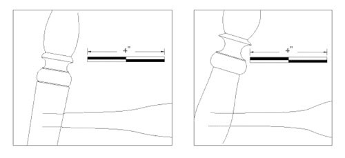
Since chairs with relatively high stretchers are fairly common in New England, it should not be surprising that many Yankee makers reinforced all of their stretcher joints with pins or nails (see table 5). Some New England makers used another technique to strengthen leg connections. The New England sack-back illustrated in figure 47 is closely related to classic Philadelphia examples. No pins or nails secure the stretchers, the arm supports cant forward about 10 degrees to lock in a relatively thick arm, the seat and the hoop are precisely sculpted, and the spindles penetrate the hoop at the 2, 3, 5, and 6 positions. At the same time, the chair has a rectangular arm rail and swelled feet like many other New England examples. As the drawing shown in figure 48 indicates, swelled feet allowed stretcher joint diameter to increase by 10 percent or more and joint length to increase by about 15 percent, giving a 25 percent or greater increase in cylindrical joint surface contact area. Therefore, the swelled foot is more than a New England stylistic variant. It is a structural innovation that made stretcher joints stronger and allowed makers to build chairs with more leg splay and higher stretchers than their Philadelphia contemporaries without using nails or pins.
Optimizing Stretcher Strength
Early Windsor chairmakers capitalized on the properties of green wood to shape their stock and strengthen the joints of their furniture. Green wood was cheaper than dried wood and much easier to turn on a low-speed lathe. As the legs shrank, they squeezed the side stretcher tenons and made strong connections; the greener the wood, the greater the shrinkage and the stronger the hold. Contemporary chair makers often glue their joints or use construction techniques that have not been documented in period Windsor construction. Michael Dunbar, for example, turns two rings in each stretcher tenon so that leg shrinkage creates a locking ring between them, a practice he observed while repairing an old ladderback chair. Dunbar also uses oversize tenons and dries them in hot sand so that they shrink less after assembly. Finally, he makes his side stretchers about one-quarter inch longer than the distance between the legs before stretcher installation would dictate, which pushes the stretchers against the legs and makes them more difficult to pull out even when loose. This practice creates a truss because the legs are well anchored in the thick seat. Nevertheless, Dunbar does not think much of socketed leg-stretcher connections:
| Socket joints are not the best way to secure two parts together. In fact, in the whole spectrum of ways in which wood is joined, there are few that are less satisfactory. As surely as wood shrinks and swells in reaction to the moisture in the air, a socket joint will loosen. It will loosen no matter what is done to prevent it from doing so. A nail, screw or dowel driven into the joint only prevents it from coming apart. These fasteners cannot keep the joint tight. More esoteric solutions, such as compressing an oversized tenon before inserting it into the socket or injecting a liquid to swell these tenons, do not last much longer.[28] |
Despite Dunbar’s assertions, many socketed leg joints have survived more than two centuries without loosening, because early makers had tricks of their own in addition to those described above. Contemporary craftsmen drill side stretcher sockets perpendicular to the leg grain, whereas some period artisans drilled them at a 45-degree angle. Makers who used the latter method obtained a double off-angle cinch when the legs shrank: the cinch every Windsor maker obtains because the leg is at an angle to the side stretcher, and a second cinch because the grain of the legs is at an angle to the side stretchers. The second off-angle cinch is more easily documented in refinished chairs.
The situation with regard to the medial stretcher is more complicated because the pullout forces are greater and the stretchers commonly fail. While two legs pull on each side stretcher joint, all four legs pull on the medial stretcher; the greater the splay, the greater the pull. Since few early Philadelphia chairs have pinned stretchers (see tables 3 and 4 ), Philadelphia makers relied on the shrinkage of the side stretchers to hold the medial stretcher. There is no data on the relative strength of such joints, but it appears that long-term strength improves as the size and gradual swell of the side stretchers increase. The angle of the side stretchers relative to the medial stretcher may also be important. If the sockets for the medial stretcher are drilled at a nonperpendicular angle to the grain of the side stretchers, additional cinching is obtained.[29]
Since the medial stretcher often failed, it would have been a logical place for makers to have used wide-ended tenons like those found in some seventeenth-century chairs or blind wedges that would have expanded and tightened the joints. Furniture historian Thomas Ormsbee reported that he had seen Windsor stretchers fitted with blind wedges, but no contemporary scholars or conservators have made a similar claim in reference to stretchers on Windsor furniture. Were stretcher failures the “coming to pieces” reported in the 1787 Rhode Island advertisement? That seems doubtful, given the confidence Philadelphia makers had in this aspect of their production. Few of the Philadelphia sack-backs cited in tables 3 and 4 have pins or nails reinforcing the stretcher joints. Given his propensity for pinning and nailing, the maker of the sophisticated sack-backs illustrated in figures 11 and 12 would almost certainly have reinforced his stretcher joints if contemporary chairs regularly failed in those locations.[30]
A New Methodology for the Study of Windsor Furniture
Aesthetic analysis tends to emphasize the distinctive or unusual, and often says more about modern preferences than period tastes. Conversely, structural analysis tends to be more objective. Connoisseurs and scholars of Windsor furniture have spent lifetimes separating chairs into regional categories, developing chronologies, and debating the skill reflected in carefully shaped arm supports, turnings, and other details. Although such considerations are important, a purely stylistic approach overlooks a salient fact: the Windsor chair was an engineering innovation—possibly one of the most significant of the eighteenth century. When evaluating Windsor furniture, period purchasers probably considered how well it worked of equal or greater importance to how well it looked.
This study introduces some of the tools needed for in-depth structural analysis and uses these tools to identify several steps in the development of the American Windsor armchair as it evolved from a rigid, failure-prone object into a lighter, stronger, and more flexible one. Some of these structural developments have been used to group and date these chairs in ways not possible using stylistic analysis. Specific failure modes have been identified and analyzed, and new criteria have been established to help determine when one chair is better made than another. Style and condition are important, but the long-term intrinsic value of a piece of furniture should depend in no small way on its ability to perform the tasks for which it was made.[31]
Appendix 1
Relative Strength of Windsor Arm Rails
For any bar in bending as on the chair illustrated in fig. A1 an equation may be written to relate stress, σy at any distance y from its neutral surface to bending moment or flexure, M.
|
σy = My/I
|
In this equation I is the second moment of inertia of the bar’s cross section, the integral of y2dA. Since y reaches a maximum at point c in the figure, stress also reaches a maximum.
|
σmax = Mc/I
|
(Eq. 1)
|
The ratio c/I depends only on cross-sectional geometry.
Equation 1 may be used to compare maximum stresses in the rails of two Windsors experiencing the same bending moment. If the first chair has moment of inertia I1 and the second chair has moment of inertia I2,
|
σmax1 Mc1/ I1
_____ = _____ σmax2 Mc2/ I2 |
|
But since both rails experience the same flexure,
|
σmax1 c1/ I1
____ = _____ σmax2 c2/ I2 |
(Eq. 2) |
Square vs. Round Rail Cross-Sections
Although sack-back Windsor rails are neither perfectly round nor perfectly square, they are considered first because the equations are relatively simple. Since the rails have the same overall dimensions, equation 2 is simplified.
|
σmax1/σmax2= I2/ I1
|
(Eq. 3) |
The formula for a rectangular cross-section can be used to provide a moment of inertia for the square cross-section
|
I1 = tw 3/12 = w4/12 o t4/12
|
where t is rail vertical thickness and w is cross-sectional width. But since t = 2R and w = 2R,
|
I1 = 4R4/3
|
For the circular cross-section,
|
I2 = pR4/4
|
Therefore, the stress experienced by the square cross-section compared with the circular cross-section is
|
σmax1/σmax2 = 3π/16 = 0.589
|
The square cross-section sees .589 times as much stress for the same applied moment or flexure. In other words, if the woods are the same, the square cross-section is about 1/.589 or 1.7 times stronger than a circular cross-section of the same size.
Rectangular vs. Rounded-End Cross Sections
A strength comparison can also be made for rails that are wider than they are thick. The second moment of the rectangular rail is known from above, but the second moment of the rail with two rounded ends is more difficult to calculate. That shape is in effect two half-rounds with a rectangular cross-section in between.
The parallel axis theorem allows us to obtain this moment of inertia. It says that the second moment of inertia of a body removed some distance from its neutral axis is its moment around that axis plus the product of its area and the square of the distance by which it is removed. With reference to figure A2,
|
Irounded end = Ihalf-round + d2 Ahalf-round
|
Since the second moment of a half-round around its neutral axis or centroid is .11R4, since the distance of that centroid above the base is 4R/3π, and since R = t/2,
|
Irounded end = .11R4 + πR2[(w–t)/2 + 4R/3π]2/2
= .03936t4 – .11292wt3 + .09817w2t2 |
The above polynomial will be referred to as Iend for the moment. Since the rounded rail has two such ends and a rectangle with thickness t and width (w–t) in between,
|
Irounded arm = t(w–t)3/12 + 2Iend
|
With the moment for the rounded rail in hand, relative strength is determined as before. Since the maximum distance, c from the neutral axis in equation 2, is the same for both rails, equation 3 applies. If subscript 1 refers to the rectangular cross-section,
|
σ1/σ2 =
|
t(w-t)3/12 + 2Iend
tw3/12 |
where Iend is defined above. This result can be simplified and generalized for any w/t ratio:
|
Rel strength = 1 – .6439(t/w) + .290(t/w)2 – .0554(t/w)3
|
This equation shows that the rail with a rectangular cross-section is indeed stronger than the rail with a rounded cross-section, but that the difference diminishes as the rail becomes wider. In the limit w/t becomes unity, the equation provides the same result as the circular vs. square analysis above.
Rectangular vs. Squared Off at Rear
The rail whose cross section is squared off at rear is considered last because its equations are the most complicated.
In the analysis above the neutral axis was also the axis of symmetry. The moments of inertia of the half-rounds were determined and then translated to the center of the rectangular area. But in this case the neutral axis must be determined before the moments can be translated. This axis passes through the center of gravity of the whole cross-section, cg.
|
cg =
|
∑iyiAi
∑iAi
|
Or, with reference to figure A3,
|
cg =
|
A1y1 + A2y2
A1+ A2
|
Figure A3 is now used to evaluate each of these terms in turn.
|
A1 =
A2 = Y1 = Y2 = |
t(w – t/2) πR2/2 = πt2/8 (w – t/2)/2 w – t/2 + 4R/3π |
||
|
=
|
w – t/2 + 2t/3π |
The terms are then combined using the center-of-gravity equation.
|
cg =
|
2(2wt – t2)(w – t/2) + πt2(w – t/2 + 2t/3π)
8wt – 4t2 + πt2
|
With reference to figure A3 this neutral line lies between y1 and y2.
Having determined the neutral axis, the moments of inertia can be translated using the parallel axis theorem as before. Again, with reference to figure A3,
|
I1 =
|
bh3/12 + A1d12 | |
|
=
= |
bh3/12 + A1(cg - y1)2 t(w - t/2)3/12 + (wt – t2/2)(cg – (2w – t)/4)2 |
|
|
I2=
|
.11R4 + A2d22 | |
|
=
= |
.11(t/2)4 + A2(y2 – cg)2 .11(t/2)4 + (πt2/8)(w – t/2 + 2t/3π – cg)2 |
The moment of inertia for the flat-back arm rail can now be calculated,
|
Iflat-back=
|
11+12 |
where 11 and 12 are defined in terms of cg and the above equations. With this moment of inertia, relative strength can be determined as before. Since the maximum distance, c from the neutral axis in equation 2, is not the same for the rectangular and flat-back arm rails, that distance must be included in the analysis. The results are not amenable to elegant simplification, as in the example above.
Figure 24 in the text shows the results of these analyses. The flat-back arm rail is a great deal stronger than the rounded arm rail, but not quite as strong as the rectangular rail.
Notes on Chair Measurements
Since measurements play an important role in this work, it is important to know how they were made. Each arm rail width and thickness measurement is usually the average of two or more micrometer measurements at the center spindle. If rail dimensions change significantly near the center spindle, it is noted in the text or the captions. Seat width, seat depth, seat height, and overall height were measured to the nearest sixteenth of an inch. Seat heights were measured to the top of the central pommel. Arm support splay angles were obtained using a protractor flush with the seat at the center of the arm support. Leg splay angles were obtained using vertical and horizontal distances defined by the center of each leg where it met the floor and a plumb bob dropped from the center of the leg flush with the underside of the seat. Left and right refer to a person sitting on a chair.
Since plumb bobs are not found in most furniture measurement kits, a simplified leg splay measurement technique may be substituted if opposing legs are symmetrical. The technique provides an incorrect average angle for Windsors whose rear legs splay more than their front legs. First the following definitions: ds is the horizontal distance between the centers of the legs under the seat, df is the horizontal distance between the centers of the legs at the floor, and h is the height of the underside of the seat at the top of the leg. Therefore, with reference to the figure, leg splay angle θ is defined by the right triangle whose height is h and whose base is (df – ds)/2.
The tan –1 (inverse tangent) function is found on most engineering calculators. To check calculator operation, enter 1.0 and press the tan–1 function. If the calculator is working in degrees, it will show 45 degrees. If one of the legs is low and the legs are symmetrical, the measurement technique is still valid.
ACKNOWLEDGMENTS
For assistance with this article the author thanks Karie Diethorn, Brock Jobe, Jane Kolter, Martin Edward Schnall, and especially Philip Zea, who asked me to think beyond the arm rail and who read many drafts. This work would not have been possible without the earlier scholarship and contributions of many students of Windsor furniture, including Charles Dorman, Nancy Goyne Evans, Wallace Nutting, Thomas Ormsbee, and Charles Santore. The article is dedicated to the late Alonzo Lee Nichols, who gave me the ability to know what I was looking at and the courage to follow my eye, and to my wife, Elaine Ulman, who started me down a long twisting path when she refused to have chairs that might come to pieces in our living room.