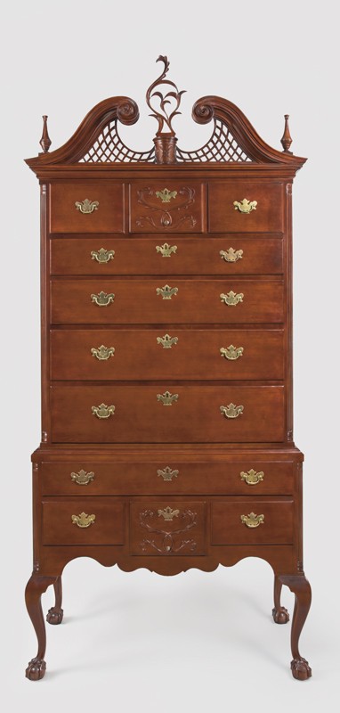
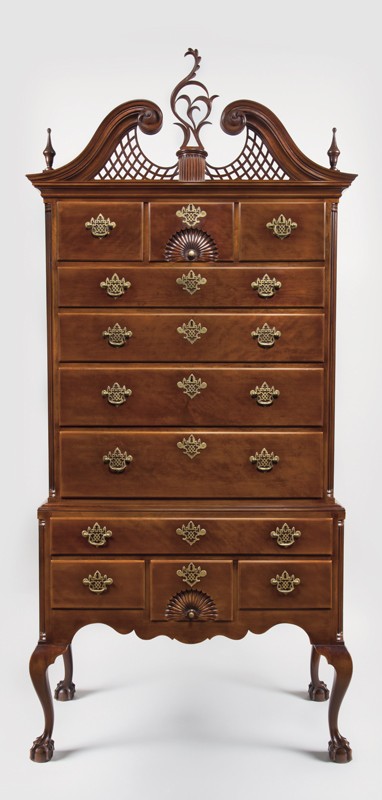
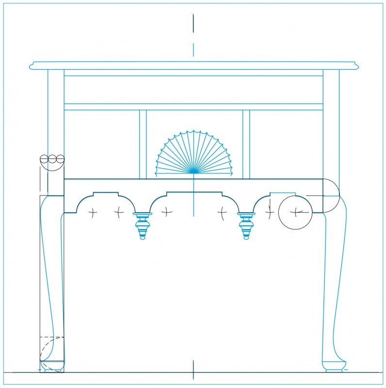
Research for this article began when Steve Brown was commissioned to a build a replica of a dressing table by Charlestown, Massachusetts, cabinetmaker Benjamin Frothingham (1734–1809) (fig. 1) and Will Neptune was hired to make a high chest in the style of East Windsor, Connecticut, cabinetmaker Eliphalet Chapin (1741–1807) (figs. 2, 3). We began by photographing, measuring, and making tracings of the furniture—a process typically followed by contemporary craftsman engaged in such projects. As our work progressed, we became convinced that we could decipher the design process of the original makers. Based on their training and the skillful execution of their work, it was plausible to assume that Frothingham’s and Chapin’s designs developed in a logical sequence of steps. Those craftsmen were also products of an era when furniture design and architectural design were intimately intertwined, in both theory and practice. With that understanding, the authors looked for clues to the development of designs in eighteenth-century furniture pattern books and architectural treatises to see how the practices and procedures revealed in those publications might inform Frothingham’s and Chapin’s work. What we discovered was that certain eighteenth-century furniture makers, including our subjects, made extensive use of classical proportioning and geometric construction and were able to design virtually every aspect of a piece of furniture starting with a single dimension and using little more than a compass, a straight edge, and a few sheets of paper.[1]
Architectural Design and Furniture Design
In the preface to the first edition of The Gentleman and Cabinet-Maker’s Director (1754), Thomas Chippendale wrote: “Of all the Arts which are either improved or ornamented by Architecture, that of cabinet-making is not only the most useful and ornamental, but capable of receiving as great assistance from it as any whatever.” Particularly important in the widespread dissemination of classical design were Isaac Ware’s 1738 translation of Andrea Palladio’s I quattro libri dell’architectura [The Four Books of Architecture (1570)], which was the most significant reinterpretation of Vitruvius during the Renaissance, and James Gibbs’s Rules for Drawing the Several Parts of Architecture (1732). Architectural historian Robert Chitham described the latter publication as “a practical textbook,” noting that it was “very different from anything that had appeared before. Apart from its entirely original method of proportioning, it . . . confined itself solely to instructing the reader in the setting out of the orders, their components and their ancillary elements.” Furniture designers ranging from Batty Langley to Thomas Chippendale to Thomas Sheraton all followed the procedures described by Gibbs for dividing, subdividing, and constructing the details of the five orders.[2]
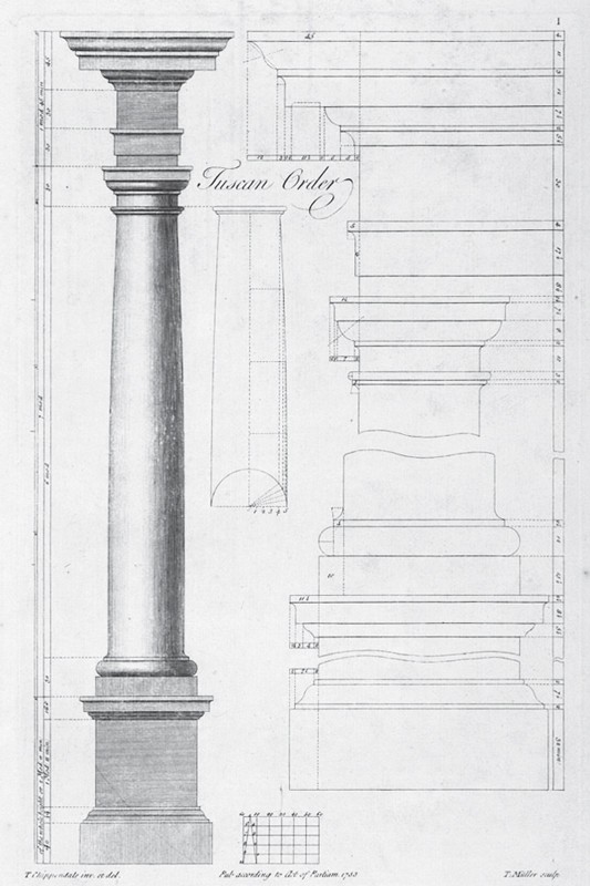
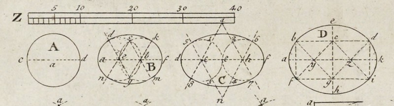
In architectural applications, the height of the building being designed is divided into five equal parts. The bottom one-fifth defines the height of the pedestal while the remaining four-fifths include the height of the column and entablature. For the Tuscan and Doric orders, this four-fifths remainder is divided into five equal parts, with the top fifth defining the height of the entablature. For the Ionic, Corinthian, and Composite orders, the four-fifths remainder is divided into six equal parts, with the top sixth defining the entablature height. With the height of the column established, it is divided into seven, eight, nine, or ten equal parts. These designate the specific orders: Tuscan, Doric, Ionic, Corinthian, and Composite, respectively. For each of the orders, one of these parts determines the column diameter at its base. This becomes a module represented by a circle, which is divided into sixty units called minutes (fig. 4). These units can then be used as whole numbers or divided into seconds, thirds, and fourths to determine the dimensions of the remaining elements and details.
Division into parts and repeated subdivision creates a series of ratios relating one element to another. This reliance on mathematical relationships is repeated in the shape of floor plans, starting with the circle and square followed by a series of rectangles, each with a distinct relationship between breadth and length. In his Squaring the Circle: Geometry in Art and Architecture, Paul Calter lists the seven shapes of floor plans derived from Vitruvius and specified in Palladio’s The Four Books of Architecture: round, square, root-2 rectangle, square and one third, square and one half, square and two thirds, and two squares. The root-2 rectangle is constructed by using the diagonal of a square as the long side of the rectangle. The square root of two is an irrational number, but like the other shapes, it can be rendered easily with a compass and straight edge. The square and other rectangles can all be described by whole-number ratios. Starting with a square—a 1:1 ratio—each subsequent ratio adds a fraction of the square to the square to form a rectangle: a 2:3 rectangle is formed by adding one half, a 3:4 by adding one third, a 4:5 rectangle by adding one fourth, and a 3:5 by adding two thirds. These ratios provided a means for organizing space, but they were also intended to resonate with the perception of those viewing a design or experiencing it if translated into three-dimensional form. English architect Sir William Chambers noted that a person’s response to a design “is not alone produced by the image on the organ of sight, but by a series of reasoning and association of idea, impressed and guiding the mind in its decision.” As he and many others saw it, an important goal of design was to have the observer perceive, or at least sense, its rational order. Chippendale alluded to this in the Director, cautioning readers that without “acquaintance with this science [knowledge of and ability to proportion and construct the ‘Five Orders’], and some knowledge of the Rules of Perspective, the Cabinet-Maker cannot make the Designs of his Work intelligible, nor show, in a little Compass, the whole Conduct and Effect of the Piece.”[3]
According to scholars Alexander Tzonis and Liane Lefaivre, “three levels of formal devices” are present in classical architecture: “taxis, which divides architectural works into parts . . . ; genera, the individual elements that populate the parts as divided by taxis . . . ; [and] symmetry, the relations between individual elements.” In taxis a designer may use a grid system or two overlapping grid systems to frame and subdivide space. Overlapping grids create divisions that alternate in size while maintaining an underlying order. Genera includes the “Five Orders:” Tuscan, Doric, Ionic, Corinthian, and Composite. Symmetry refers to “relations between individual elements” based on systems of mathematical order—typically ratios and proportions—rather than simple mirror imaging. In mathematics the words “ratio” and “proportion” have distinct and separate meanings. A ratio compares two values, whereas a proportion is the equivalence of two ratios. For classical architects, these formal devices had practical and aesthetic implications, allowing practitioners like Vitruvius to design works of “firmitas, utilitas, venustas.” Seventeenth-century writer Henry Wotton translated that phrase as “firmness, commodity and delight,” but later interpretations would probably express it as “strength, utility, and beauty.”[4]
All of the aforementioned scholars emphasized the importance of building layers of order, using mathematical relationships to produce symmetry in the Vitruvian sense. As Chambers noted, an object’s appeal is not only to the eye, but also to the rational mind. Eighteenth-century furniture makers understood that as well. Chippendale described the study of classical architecture and the five orders as a “science” which, when combined with an understanding of perspective and geometric construction, constituted “the very soul and basis” of the cabinetmaker’s “art.” He also realized that many of his patrons were well–versed in classical architecture and had significant portions of their libraries devoted to that subject.[5]
By studying and learning how to draw the orders, a cabinetmaker would acquire several valuable skills: the ability to work neatly and accurately with a compass (or dividers) and straight edge; comprehension of the systems of division used to establish the pedestal, column, and entablature; the ability to produce an accurate scale and use it to measure dimensions on a drawing; and an understanding of geometric constructions used to create curved elements with a compass, such as the volute in the Ionic capital or the various moldings associated with each order. Many design books provided information to assist builders and cabinetmakers in drawing the orders and other aspects of design. Batty Langley’s The Builders Compleat Assistant, or, A Library of Arts and Sciences, Absolutely Necessary to be Understood by Builders and Workmen in General (1738) explains and illustrates numerous problems in mathematics, geometry, and drafting.[6]
Competence in drawing and the mathematical skills required for proportioning and geometric construction alone did not ensure good design. Aesthetic choices made within ordered systems had a profound impact on the final product. Modern concepts of design often see structure and restriction as antithetical to creativity, but the more important distinction is between form and content. As Chitham notes: “the orders as a whole form a complete system analogous to a language, abiding by rules of grammar and syntax, capable of being used in a literate manner, but vulnerable to illiterate abuse.”[7]
Practical Application
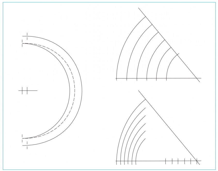
If a design can be rendered with a compass and straight edge and the size of parts relate mathematically, it is a straightforward process to transfer information from a scale plan to the work piece. This applies to both subdivision of a line into fixed units and the geometric constructions of curved elements. Constructing curved elements with compass and straight edge has important technical advantages. A curve is considered fair if it has a regular and uninterrupted flow. Unlike freehand curves, compass constructions will be fair if the designer follows simple rules of geometry. By simply changing the radius, the shape can be scaled up and down. A curve may be laid out on a scale plan or directly on a full-sized work piece or full-sized pattern. Eighteenth-century tools such as gouges and molding planes readily conform to compass-drawn designs as they were made to cut sections of circles. Furniture designs often have nested curves that must maintain a consistent width apart. If the first curved line of the design is drawn with the compass, any related lines will use the same compass points. These offset problems are more difficult with non-circular and freehand curves.
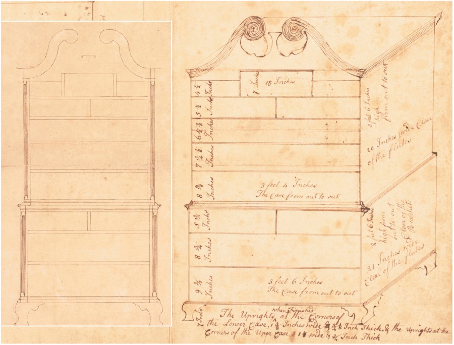
A small group of drawings associated with the shop of Philadelphia cabinetmaker Jonathan Shoemaker and his journeyman Samuel Mickle shed light on the ways craftsmen developed their designs. Most important to this study are a formally drafted scale drawing of a chest-on-chest (fig. 5) and a second in rough perspective (fig. 6). The perspective view provided a place to record dimensions for the facade and sides, and those dimensions correspond with those present, but not indicated, in the formal scale drawing. The equivalence of the two drawings is not obvious for two reasons: the case widths in the perspective view are drawn much wider than they should be, distorting the appearance of the chest-on-chest, and this drawing lacks the corner columns seen in the formal elevation. But the notations across the bottom of the perspective view list the size of “The Uprights at the Corners of the Lower Case, 1 3/8 Inches wide & 3/4 1/8 Inch Thick” (the latter dimension is a way to express 7/8") and repeat the instructions for the smaller upper case uprights. These narrow pieces are the vertical members that would be joined to the notched-out drawer rails to create an inside corner for the turned columns. It is possible the design was offered in two versions, depending on the patron’s taste and budget, or that Mickle knew how he would build the front corners of the two cases and felt no need to draw them.
The formal drawing may have had two purposes. It would have allowed Shoemaker to work out the overall height, rectilinear divisions for the two cases, and curves of the pediment and feet. This version could have been shared with a patron to secure approval for the proposed case piece and demonstrate the cabinetmaker’s competence in design. By converting the scale drawing to foot and inch measurements, Shoemaker would have made it possible for his workmen to build the chest-on-chest correctly without seeing how the sizes and divisions of space were developed. Separating the two drawings may have been his way of protecting his design procedures.
If Shoemaker’s training followed the approach recommended by Chippendale, he would have understood the architectural orders and been able to incorporate into his design the mathematical relationships they represent. The formal drawing could have been drawn at any arbitrary size with a scale provided to allow conversion to full size. But Shoemaker chose to render the combined upper and lower cases 12" tall. Using a simple scale of 2" equaling 1 foot (2:12 = 1:6) allows very convenient divisions using the written dimensions from the perspective sketch (42" = 7" and 30" = 5"). This supports the case that Shoemaker intended the combined case heights to be 72" and that the two drawings are of the same design.
Measurement and analysis of the formal drawing reveal Shoemaker’s design process. The notations on the perspective drawing make it possible to confirm the divisions and locations detected in the formal scale drawing; however, it is important to remember that all of these divisions can be generated graphically and require no calculations. The process of determining the sizes for the required elements could be worked out on a separate piece of paper using dividers and a straight edge and the dimensions transferred to the final drawing. Choosing the seven-unit divisions of the Tuscan order as the basis of his design, he began with a height of seven feet (84") (fig. 7). In the architectural orders, the module is defined by the diameter of the column at its base and is represented by a circle. Drawing the seven 12" scaled modules next to the Shoemaker drawing (on the left side) shows that the pediment is one module high and the division between the two cases falls on the radius of the third module up from the bottom. This makes the upper case seven radii tall, repeating the division of the Tuscan order. Using the radius as a diameter (a simple 2:1 ratio), the upper and lower cases can be shown as seven and five new submodules respectively (fig. 7). The heights of the two cases form a 7:5 ratio. Of the ratios available from the five orders, the Tuscan is the only match for these dimensions.
With five orders available, why would Shoemaker have chosen the Tuscan order as the basis of his design? Being seven diameters high, the Tuscan order might be considered more robust than the others, which become increasingly slimmer. The Tuscan order also has the simplest embellishments, thus giving it a more austere presence. The choice of order is related to the character and effect of the intended design.
The top 12" module on the left in figure 7 is divided into four parts, with one additional part giving the width of the pediment molding (3"). This makes the pediment five units tall (15"), with the bottom fifth lapped over the upper case. The lower case is also divided (on the right) into four parts (30" ÷ 4 = 7.5"), and a fifth unit becomes the height of the bracket feet (including the pads, which are not shown in the perspective sketch), making the total height 37.5". This establishes a submodule for the lower case. These five modules for the lower case, with feet, repeat the original division of the lower case (without feet) using five radii. This sequence of division and subdivision defines all of the major elevations used in the design and creates mathematical order between the whole and all of its parts.
The width of the lower case is 42", which equals the height of the upper case, forming a 1:1 ratio. On the left side of the drawing the height of the upper case is represented by seven submodules (6" diameter), which are also drawn across the bottom. One of these units is divided into thirds (2" on the bottom right). Subtracting a 1/3 unit determines the upper case width, stepping in 1" on each side. These divisions are drawn across the upper case. The four lower case submodules above the feet (on the right) are each divided into four parts (7.5" ÷ 4 = 1.875"). This locates the base molding and drawer rail at the bottom and the cornice molding and rail at the top. This dimension is divided in half (1.875" ÷ 2 = 0.938") and determines the thickness of the other rails. The lines for these divisions are also used as elements of the moldings at the top and bottom. The inside edges of the corner column uprights are 37.5" apart, equaling the height of the lower case. The columns and uprights are 2.25" wide (42" - 37.5" = 4.5", 4.5" ÷ 2 = 2.25"). This matches the perspective view, which notes the sizes of the 1 3/8" column and 7/8" upright (shown as 3/4" 1/8"). The modules also determine the projection of the bracket feet.
The 30" height of the lower case (without feet) is divided into seven parts using the divisions of the Tuscan order, just as was the upper case. Two of these parts locate the bottom of the second rail (30" ÷ 7 = 4.286", 4.286" x 2 = 8.572"). With the rail thickness of .938" and the top two layers being 1.876", the opening is 5.758", which is a .008" error from the 5.75" shown in the perspective drawing. The top space is divided into two equal, side-by-side drawer openings. The space below this is divided into the middle and bottom drawer openings, which are graduated by one inch, making them 8.807" and 9.807" respectively. These dimensions are very close to the sizes given in the other drawing (8.75" and 9.75"). The dimensions calculated from the proportional divisions of the lower case total exactly 30". The discrepancies with the perspective view dimensions suggest that drawer openings were rounded to a simple fractional size.
The process of dividing the upper case begins with establishing the lower edge of the tympanum panel below the pediment (fig. 8). The 15" total height of the pediment is divided into seven parts (15" ÷ 7 = 2.143"), repeating the use of the Tuscan order. One half of this unit (2.143" ÷ 2 = 1.072") is added below, using the radius to locate the bottom edge of the panel. The 42" case height is divided by seven (42" ÷ 7 = 6"), and then this dimension is again divided by seven (6" ÷ 7 = .857"), giving the thickness of the upper case drawer rails. The bottom of the first rail is three units (of the pediment divisions) below the pediment molding (2.143" × 3 = 6.429"). Subtracting the rail thickness and the flat below the molding leaves 4.5" for the top drawer opening, (6.429" − .857" = 5.572", 5.572" − 1.072" = 4.5"). This corresponds to the stated dimension in the perspective view.
The upper case below the first drawer is then divided into four more drawer openings separated by drawer rails measuring .857" thick. The other drawers follow a progression starting with the 4 1/2" side drawers, adding one inch to make the second drawer 5 1/8", adding 1 1/8" to make the third drawer 6 5/8", and adding 1 1/4" to make the fourth drawer 7 7/8". The bottom drawer fills the remaining space, which is 8 5/8" after allowing for the case bottom and last drawer rail; the bottom rail and case bottom are each .857". Adding all of these divisions together totals 42.089", which is .089" more than the intended 42". The error would be distributed among the five drawer openings, changing each by .018", or .003" per opening at the 1:6 scale.
The width of the top center drawer opening equals the 15" total height of the pediment. The 3" pediment molding height is divided in half and a line is extended to locate the top of the center drawer opening, making it 6.985" tall. The perspective drawing gives this size as 7", an error of .015", or 0.003" at scale. This may be from rounding the size to a convenient inch dimension. The two flanking partitions are the same size as the flat above the side drawer openings (1.0715"). The dimensions of the columns and uprights are determined by dividing the 15" width of the center drawer opening by four and dividing the result in half, with one part for each side (15" ÷ 4 = 3.75", 3.75" ÷ 2 = 1.875"). This matches the size noted on the perspective view (1 1/8"+ 3/4" = 1.875").
The pediment is developed using the 12" module height and the 15" total height of the pediment molding (fig. 8). The 12" module is divided by three to determine the center plinth height of 4". The 15" height of the pediment molding is divided by seven to create smaller divisions. A horizontal line is drawn four units down from the top to locate a point on the centerline. An arc with a three-unit radius is drawn using this point as a center. A second horizontal line is drawn three units from the top. The points where the arc crosses this line are the centers for the three-unit arcs that form the upper curves of the pediment. The outer arcs of the molding are also three-unit circles, drawn tangent to the top of the case and the first two circles, completing the S-curve. The same four compass points are used to draw the arcs that form the lower edge of the S-shaped molding. The width of the case is divided by six and the space between the knuckles is one 1/6 unit. The knuckle circles use the 1/7 module as a radius and are drawn making the knuckles touch both the top S-curve and 1/6 center space.
In Shoemaker’s design, every part is mathematically related to every other part, and visual complexity accumulates step-by-step. He used the seven-part division of the Tuscan order at every stage to establish proportional symmetry. The design contains a remarkable amount of information, yet Shoemaker employed only four strategies:
• Division by the seven-module Tuscan order
• Whole-number proportional division
• Determining drawer openings using a progression
• Drawing of arcs and concentric arcs (for the pediment)
These strategies did not eliminate choice or creativity. The decisions he made and the orderliness of his design demonstrate a commitment to the approach recommended by Chippendale.
Reverse-Engineering the Design Process
Analysis of the Shoemaker and Mickle drawings suggests that the design process of certain period cabinetmakers can be reverse-engineered. If a maker followed a “classical” approach rigorously and his workmanship was competent and consistent, nearly every dimension, location, and curve in his work should reveal mathematical relationships and interdependence. Attempting the accurate determination of such relationships is not without risk. In Squaring the Circle: Geometry in Art and Architecture, Paul Calter presents undertakings by eight separate authors to analyze the geometry of the Parthenon and identifies two failings. The first concerns the locations from which measurements should be taken, which in a structure of that complexity is problematic. One person might measure to the top of the entablature, whereas another might measure to the edge of the roof overhang. The second failing centers on the accuracy of measurements, particularly when working with scaled-down representations, wherein overlays of rectangles or other geometric constructions have greater potential to disguise errors. A more obvious risk, inherent with many types of inquiry, is the temptation to make evidence fit a theory. An Internet search on the “golden section” will provide the reader with numerous cautionary examples. Specific to research on classical architecture and the furniture inspired by it, rectangles in the ratio of 3:5 are sometimes identified as a “golden section.” Vitruvius and the architects of the Italian Renaissance do not appear to have mentioned the “golden section,” but they did refer to a variety of rectangles with whole-number ratios, including the 3:5-rectangle. All of the above examples illustrate “closely linked methodological problems” that Robert Bork addresses in The Geometry of Creation: “imprecision, ambiguity, and wishful thinking.”[8]
To mitigate such problems for this study, the authors established strict standards for analysis and interpretation. Accurate measurements and full-sized tracings were essential, but we also stipulated that any mathematical relationships or geometric constructions observable in an object had to be reconciled with the maker’s standards of workmanship. For example, in analyzing a photograph showing the front view of a chair from a set, it might appear that the maker designed it to fit within a 1:2 ratio rectangle. Measurements of the height and width of chairs from that set would show the variation allowed by the maker. If he was working to a given tolerance, the height and width should conform to the proposed rectangle within that tolerance. Discrepancies can result from several factors, including the use of period tools and techniques. A layout system that marks a series of separate dimensions might have a large error that represents an accumulation of several smaller ones. Similarly, errors double in spindle turning; cutting deeper by 1/16" removes that amount from the entire circumference, making the diameter smaller by 1/8".
For description and analysis, the authors used the following tools and methods:
• Dimensions under 6" were taken with a plastic dial caliper, calibrated to .001", where possible. This was done either directly on the piece or on a casting made from a silicone rubber mold of the original.
• If allowed, dimensions up to 79" (200 cm.) were taken with a folding plastic ruler whose accuracy was checked against a 48" machinist steel rule. The ruler was marked in both inches with 1/32" divisions and a metric scale of centimeters and millimeters. Measurements taken in millimeters were later converted to inches.
• If the folding ruler was not allowed, strips of Bainbridge board were held against the piece and marked with a pencil. These marks were then measured with the ruler.
• Curved components were scribed directly onto paper, poster board, or Bainbridge board. Over the course of their research, the authors found that the best solution was to mount paper temporarily onto Bainbridge board using low-tack repositionable spray adhesive. This gave a firm backing to trace against but allowed the authors to remove the tracing, which could be scanned and printed. This meant that analysis could be done on the copies, preserving the original tracing.
• Full-scale prints of photographs were used only when a scale was included in the photograph, to identify distortion.
The Design Process of Eliphalet Chapin
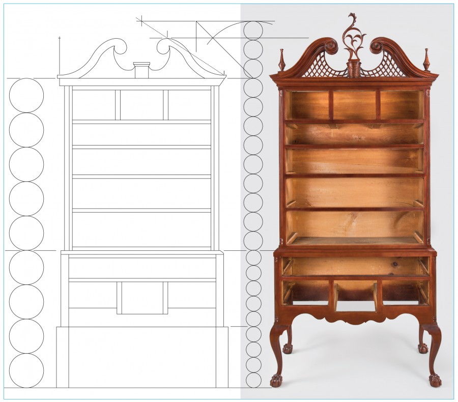
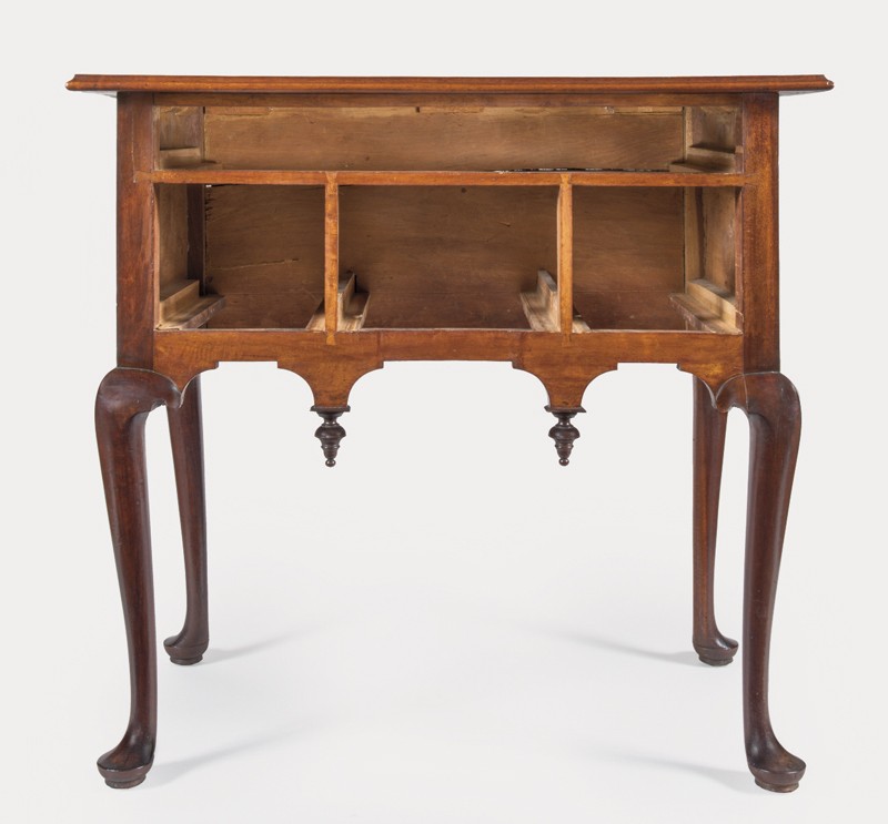
The high chests measured and examined for this study are in the collections of the Wadsworth Atheneum and Winterthur Museum (figs. 2, 3). The upper and lower cases of the example illustrated in figure 2 were separated and used by different members of the family through which that object descended. The lower case probably had a top added to it, and the upper case was probably fitted with feet and a base molding for use as a chest of drawers. The scroll moldings were cut a few inches from each end, suggesting that they were removed, a straight piece of molding was inserted to fill in the gap, and a board top was added. Connecticut collector Robert P. Butler purchased both pieces and commissioned their restoration, including reattachment of the scroll moldings, which had been saved by the family. The saw cuts and adjustments made during the restoration changed the molding locations and the way the latticework meets the central plinth. This complicates any attempt to determine the design process for the pediment. The high chest illustrated in figure 3 was added to this study because it has an unaltered pediment.[9]
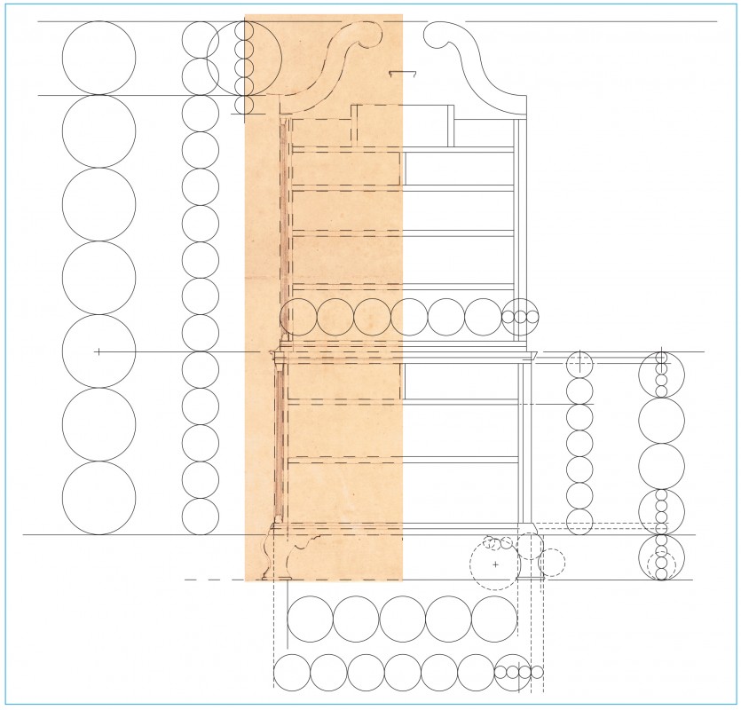
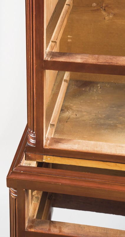
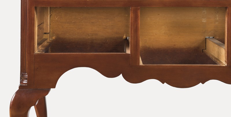
Identifying mathematical relationships in the high chests is complicated by two construction details. The bottom of the upper case rests on the tops of the legs and upper rail and sides of the lower case. The waist molding is glued to the top edge of the lower case and mitered at the front corners, thus concealing the dovetailed bottom board of the upper case. A cherry front rail and white pine drawer supports of equal height are glued to the inside of the bottom, and the rail is visible above the waist molding (fig. 9). The visual effect is that the rail is the bottom of the upper case and that the upper case rests on top of the waist molding rather than inside it. This creates two possible points from which to measure: the top of the leg and the top of the waist molding. A similar issue occurs at the top of the upper case. The top board is concealed by the side cornice moldings (fig. 10), but from the front view the top of the front cornice appears to be the top of the case with the pediment assembly mounted above. Chapin reinforced this effect by chamfering the top board to allow light through the lattice and hide it from the front view (fig. 11). This pediment design provides two choices for taking measurements: the top of the case or the top of the front cornice molding.
On the lower case, the leg extends from the floor line to the bottom of the waist molding. The stiles are flat and square with a rabbet for the quarter column. The top, mid- and bottom rails join the square leg post, giving the visual effect of a rectilinear box sitting on top of curved legs. This visual effect is important and makes the top of the knee a significant elevation for taking measurements of horizontal divisions.
A Theoretical Model for Chapin’s Design
A theoretical model for Chapin’s design process can be posited by analyzing significant dimensions taken from the high chest illustrated in figure 2. For that furniture form, he appears to have chosen the Ionic order and a height of 72", measured from the floor to the top of the front cornice molding. This represents a 3/16" to 1/4" variance from the high chests, but if Chapin prepared a scale drawing similar to Shoemaker’s and based his design on the Ionic order, he would have wanted to begin with a height that was conveniently divisible by nine and ensure that his drawing would fit on a reasonably sized piece of paper. A scale height of 9" is an obvious choice, but that would have been more difficult to draft. A good compromise would be 13 1/2", with 2 1/4" equaling one foot. Compared to Shoemaker’s reliance on the Tuscan order, Chapin’s choice of the Ionic would suggest a design that reflects the slender column and more complex embellishments found in this order.
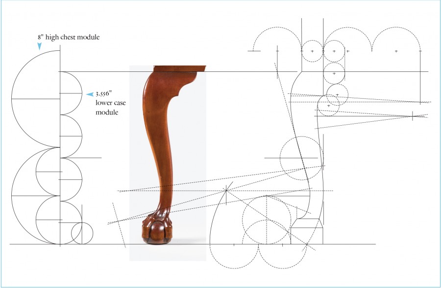
As shown on the left side of the drawing illustrated in figure 12, dividing by nine produces an 8" module. Five modules (40") determine the height of the upper case, using measurements taken from the top of the waist molding to the top of the front cornice molding (actual 39.813"). Four modules (32") determine the height of the lower case, using measurements taken from the floor to the top of the waist molding (actual 32.047"). On the right side of the drawing, the height of the lower case is again divided into nine parts, giving a second smaller module (3.556"). Five modules give the height from the top of the knee to the top of the waist molding (17.778", actual 17.756"). Four modules give the height from the floor to the top of the knee (14.222", actual 14.291"). The divisions of the lower case, including the waist molding, restate the divisions of the entire case piece. Algebraically the ratio used is 5:4. The module for the entire high chest is larger than the module for the lower case, but both start with nine parts and are divided into five and four parts. This is an example of symmetry, as described by Tzonis and Lefaivre; these relations are the mathematical order that is developed in the design in the form of ratios and proportions. When dividing the height of the upper case by the height of the lower case, one arrives at the same number as when dividing the height from the knee to the waist molding by the height of the floor to the knee (40 ÷ 32 = 17.778 ÷ 14.222 = 5÷4). As Sir William Chambers noted, observers can appreciate the beauty of a design by “reasoning and association of idea.” Classical architecture uses proportion—stating and restating a relationship—to create a sense of mathematical order in the design. Chapin used a 5:4 proportion to create order among the various elevations of the high chest, establishing these relationships using the Ionic order.[10]
Additional layers of order can be developed in the widths of the upper and lower cases. In the drawing shown in figure 13 the module for the entire high chest is represented by a circle. Drawing a circle to indicate a diameter requires a compass setting for the radius. The relationship between radius and diameter is expressed by the ratio 1:2. The width of the lower case to the outside of the leg blanks equals five 8" modules (drawn across the bottom) as does the height of the upper case, producing a 1:1 ratio. The width of the upper case is stepped in from the lower case by one radius of the module (drawn across the front of the upper case) giving a ratio of 9 radii (36", actual 35.906") to 10 radii (40", actual 39.961") between the upper and lower cases.
The drafting of Chapin’s pediments relates to plate 12 in William Pain’s The Builder’s Companion, and Workman’s General Assistant (1758) (fig. 14). The engraving shows the centerline with a point marked and the line below labeled 1/4. A second line connects this point with the outer tip of the cornice molding and crosses the S-curve molding at its highest point. This sloped line is the rake angle and meets the center line at the rake point. Following the language for constructing the architectural orders, the “1/4” refers to its being a new fourth part, rather than a quarter of some previously used division. In other words, the combined heights of the upper case and rake point equal four parts. The lower three fourths are the height of the upper case measured to the top of the front cornice molding. If the height of the upper case is divided into nine Ionic modules, there are three sets of three diameters making up the three-fourths height of the upper case. Three more of these modules are the height at the centerline of the marked point above the pediment in Pain’s engraving. Scaled up to full size, the upper case is 40" tall. Division by nine gives a submodule of 4.444", with three of these modules equaling 13.333". In the engraving, Pain uses a geometric construction of triangles and arcs to determine the highest point on the curved molding and its location relative to the width of the upper case. Chapin used a different approach, constructing a root-2 division of the 13.333" height, which equals 9.428" (actual 9.372") (figs. 12, 15). Validated by their appearance in Palladio’s work, root-2 constructions offer the designer intermediate sizes relative to the radius and diameter of the module. For example, the high chest module of 8" offers the designer both the 8" increment and its radius of 4". Dividing the 4" radius by √2 = 2.828. Multiplying the 4" radius or dividing the 8" diameter by √2 = 5.657. Multiplying the 8" diameter by √2 = 11.314. It is important to remember that these apparently complex algebraic computations can be performed with the dividers or compass simply by swinging arcs. The designer could make a temporary ruler with the radius and diameter of the module marked along with the three related root-2 constructions. This offers five choices to determine the size of a given part with the guarantee that the result maintains a geometric relationship to the original order and its module. So the diagonal line from the 13.333" mark to the outer tip of the side cornice molding passes through the new elevation line 9.428" up from the front cornice molding. This crossing locates the highest point of the S-curve molding in a manner similar to the one that Pain suggests. At this stage Chapin would have established all of the elevations and horizontal divisions that determine the boundaries of the two cases and pediment. This entire design progression is a series of whole-number and root-2 divisions generated by the unit circle of the Ionic order. The modules control the overall height and width of the upper and lower cases, as well as the division of the lower case at the knee. These relationships can be developed and represented graphically using only “the rule and compasses” as Vitruvius instructed. It is not necessary to assign measurements to any of the dimensions or to do calculations in the design stage. The ratios and proportions will be true at any scale.[11]
As the drawing shown in figure 13 indicates, the lower case is divided into three parts and also into four parts. These whole-number divisions create the overlapping sets of grids of taxis. As is the case with many high chests, the center drawer is taller than the flanking drawers, creating visual variety and offering a larger surface for carving. The bottom rail is cut away in the middle to create a larger opening, which is framed on both sides by the partitions. On the outer ends, the theoretical one-fourth division is 4.445". At the center using the radius of the division into three parts, the theoretical dimension is 2.963". The actual dimensions taken from the high chest illustrated in figure 2 are 4.409" and 2.953", respectively, and are very close to the theoretical dimensions. If Chapin merely wanted a change in the heights for the side and center drawers, a range of sizes could achieve this. Additionally, either dimension by itself could be a coincidence, but taken together they make a strong case for these two whole-number divisions of the height. These divisions continue the process of building mathematical order into the design.
In the theoretical model, the case above the knees is also divided into nine submodules as in the Ionic order, and the middle drawer rail is centered on the radius point of the fourth module from the top (32 ÷ 9 = 3.556, 3.556 × 5 = 17.778, 17.778 ÷ 9 = 1.975, 1.975 × 3.5 = 6.913") (fig. 13). The actual dimension is 6.890", representing only a .023" deviation from the theoretical model. Additional geometric constructions determine the width of the three drawer openings, using arcs swung from the diagonals of the squares drawn at the floor line (fig. 12). The half circle that determines the squares is the original 8" module that divided the entire high chest into five and four parts. The root-2 constructions locate the centerlines of the two partitions that frame the center drawer opening (the center module has a 4" radius). Each quarter circle is multiplied by √2 (4 × √2 = 5.657, 5.657 × 2 = 11.314). The thickness of the partitions is larger than one might expect seeing only the drawer openings. The drawers are lipped so that the molded edge overhangs the opening on the sides and top. Chapin used the same size rabbet to create the lip on all three surfaces. On the horizontal drawer rails, which are 7/8" thick, the bottom edge is covered only by the top lip of the drawer below. But the vertical partitions will be covered on both sides by the lips of the side and center drawers. Chapin made the partitions 1 1/8" thick, so the partitions would appear to be 11/16" thick and match the appearance of the dividers. These factors determine the 10.189" width of the center drawer opening, which is close to the actual opening of 10.157", given the possible double error from the construction. The upper case drawer openings follow a simple whole-number progression, starting with the bottom drawer opening, which is one module tall (8") and subtracting one inch for each opening above. The top row repeats the seven-inch height (8" – 7" – 6" – 5" – 7"), and these three horizontal drawer openings are divided into thirds. The two partitions repeat the thickness used in the lower case.
Small increments are required to draft the cornice moldings and the drawer rails. The 8" module is subdivided into nine parts, repeating the design of the Ionic column. This gives a unit size of 0.889". Two of these units give the height of the front cornice molding (0.889" × 2 = 1.778"). Multiplying this by √2 gives the added height of the ogee element (1.778" × √2 = 2.514"). The total projection is also 1.778". These dimensions are very close to those on the high chest illustrated in figure 2, which are 1 3/4" × 2 1/2". In practice, the theoretical dimensions were probably rounded to convenient fractional sizes. In the same manner, the 0.889" height of the nine-part divisions would have been rounded to 7/8", which determined the drawer rail thickness.
The drawings illustrated in figures 12 and 13 show the main drafting and layout strategies Chapin used for rectilinear dimensions in the high chest. Whether he began with a scale drawing or story poles, he would have a record of those dimensions. Geometric constructions used to determine linear measurements as seen in the lower case center drawer could be drawn in scale to arrive at the correct dimension and then scaled up for the story pole. It is also possible that the construction with compass and straight edge would be done full-scale to achieve greater accuracy than might be achieved by scaling up from a drawing. Such full-scale constructions would require a fairly large work surface. A cabinet shop with work in progress will have boards that have been initially planed flat from rough stock, then stacked with spacers to allow them to adjust their moisture level. This process may take days or even weeks, so there are almost always boards providing temporary work surfaces. A trammel beam works like a compass but can be used for much larger settings. The root-2 constructions required for the center drawer opening could be done with a trammel beam at full scale and transferred to the story pole. This temporary layout would be planed away, having served its purpose without wasting lumber.
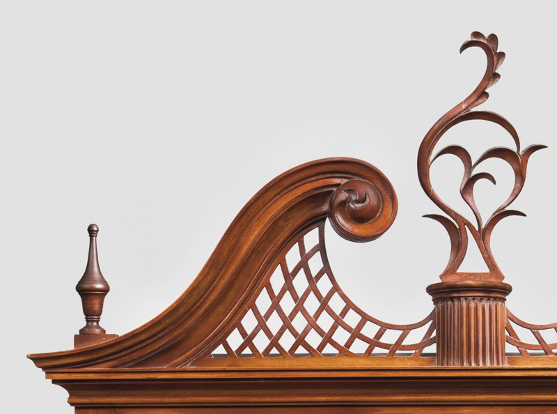
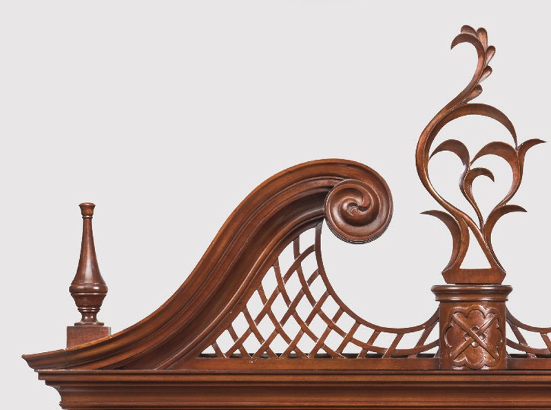
Drafting Curved Components: Pediments
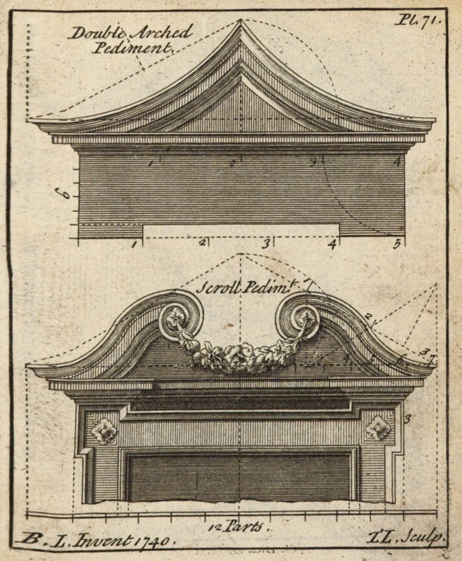
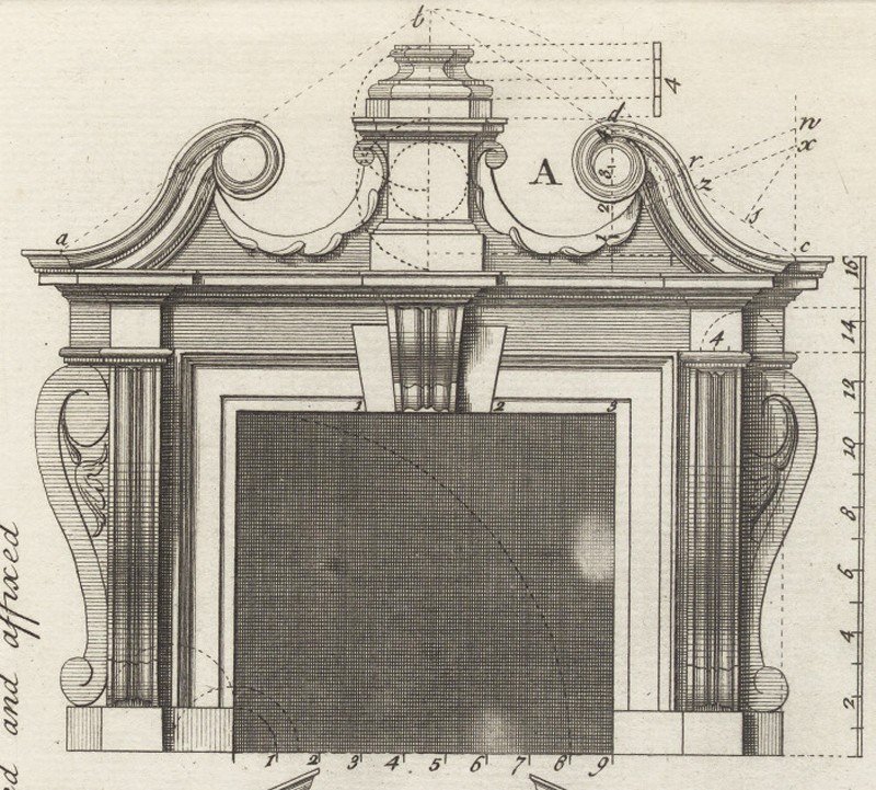
The pediments of the high chests are their most dramatic feature (figs. 2, 3, 15). Pain and Langley illustrate many pediments with S-curved moldings, or what the latter designer referred to as a “Scroll Pediment” (fig. 16). When the engravings show constructions they are usually in the form of two triangles, one for each curve making up the S-shape (fig. 14). These give the compass points for each curve and are on opposite sides of the molding. A dotted line connects these two points to show the point of transition in the curve. One plate in The City and Country Builder’s and Workman’s Treasury of Designs (1741) does not follow this convention (fig. 17). Instead it shows a pair of parallel lines with each connected to only one of the compass points. To be tangent and therefore fair curves, the space between the pair of dotted lines must be straight. Graphically this is a way to elongate a curve, sliding the concave and convex elements apart by stretching the typical point of transition so that it becomes a line.[12]
Curved elements are typically developed as full-scale patterns, allowing the shapes to be transferred to a work piece. Cutting curved elements from a thick board with a frame saw is laborious and wastes a lot of wood. It also entails risk, since sawing out of square causes a larger error. Chapin’s solution was to build the molding in two layers, hiding the glue line on the inside corner of the fillet. This method required a different pattern for each layer; both layers have the same curve on the top edge, but their lower edges differ because of the change in width. Chapin used the same compass points for all the edges, changing only the radius to establish each one.
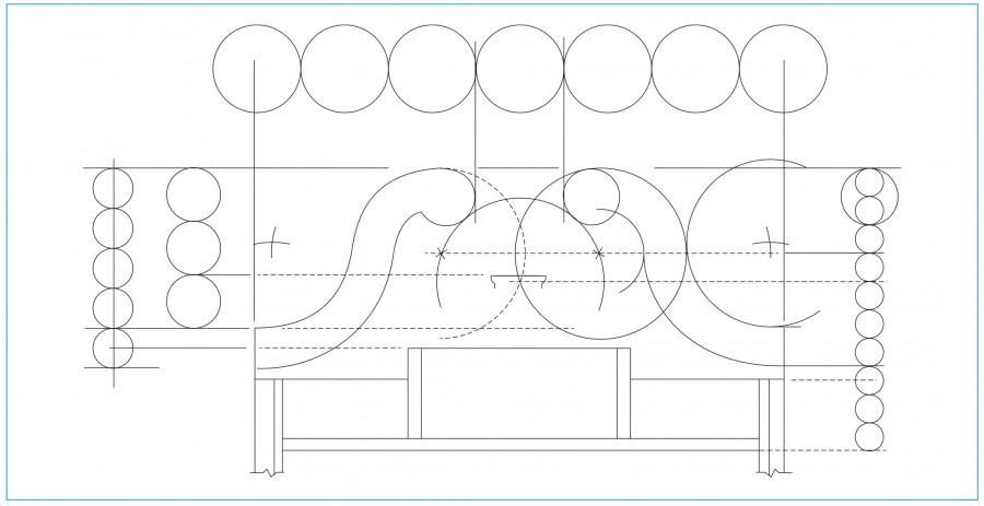
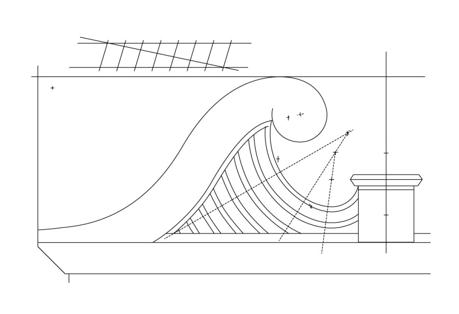
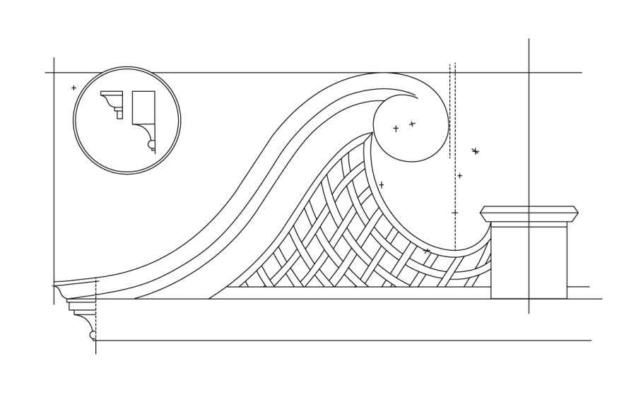
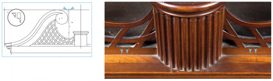
The flat section shown in the Langley plate must be tangent to both curves for the entire shape to be fair (fig. 17). Because the curves sweep less than a quarter circle, the flat in the middle is tipped rather than vertical. Finding the compass points to draw the two curves for Chapin’s pediment also identified this short straight segment. Projecting two parallel lines across the pediment, with each line beginning at one of the two compass points, creates a rectangular zone across the lattice panel (fig. 18). The piercings inside this zone have two straight edges, and all of them are parallel to the original flat section of the pediment molding. This means that the diamond shapes are not arbitrary but rather directly related to the geometry of the pediment they join.
The upper curve of the S-curved molding joins a third arc with a smaller radius that curls over the high spot and down the other side. The top edge of the lattice panel is also made up of three curves with progressively smaller radii, but these three curves do not contain an S-curve like the pediment molding (fig. 19). This gives the edge of the lattice panel the appearance of accelerating down from the scroll and then tightly sweeping up to the center plinth. The three compass points used to draw the top edge of the lattice, together with the three points used to draw the pediment curve, and its straight section, are used to draw all of the piercings inside the lattice. The straight-sided piercings are drawn parallel to the flat in the S-curve. All other curved elements are drawn using a combination of the three points forming the S-curve and the three points forming the edge of the lattice panel (fig. 20). Using three radii for both curves gives them the appearance of acceleration, making the entire effect more dynamic. As seen in the drawings from Shoemaker’s shop, a remarkably short list of constructions allowed Chapin to draw all of this information for both the pediment and the lattice panel while maintaining a geometric connection between them.
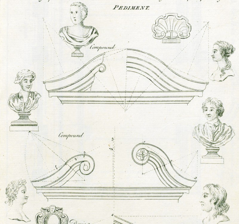
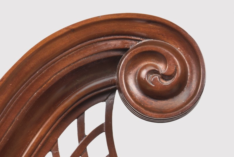
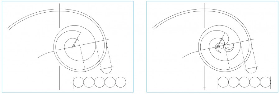
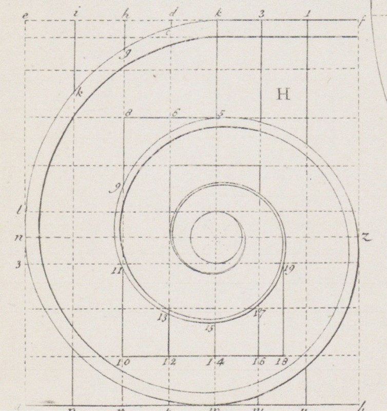
The top of the pediment molding ends in another accelerating curve, carved as a scroll of leaves (figs. 21, 22). Simple drafted versions of spirals are shown in Batty Langley’s The Builders Compleat Assistant (1738), but extremely complex spirals appear in the volutes of the Ionic capital depicted in that publication (fig. 23). In Chapin’s design, there seems to be a deliberate aesthetic connection with that order, particularly in his drafting of various curved elements.
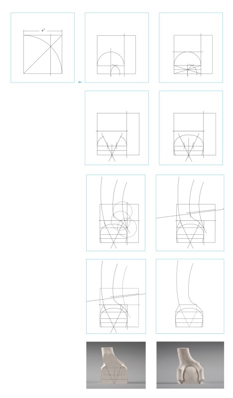
Drafting Curved Components: Scalloped Rails and Cabriole Legs
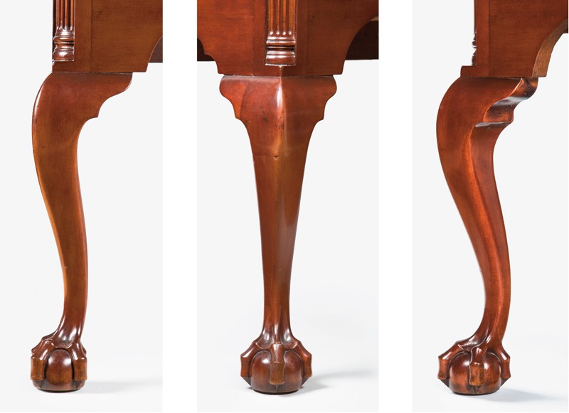
On the Chapin high chests, the curves of the lower front rail are based on a module dictated by the height of the leg. The top of the knee divides the lower case into two horizontal units so that structurally the bottom rail is part of the case above the knees. But observing the negative space below the rail and between the legs shows a rectangle above the floor decorated on three sides by curved elements: the cabriole leg, the transition block, and the rail itself (fig. 24, 2). The use of the module for the cabriole leg, rather than one from the case above the knee or of the entire lower case, supports this interpretation. Organizing the design following diagonal lines that point to the center along the bottom edge has the visual effect of cradling the tall central drawer (fig. 25). This drawer front is a focal point in the lower case and can be carved with a deeply curved lobed shell pattern or with a pair of interlaced stems with leaves. The drawings and illustrations shown in figures 26–29 show how Chapin systematically designed each feature of the high chests’ cabriole legs.
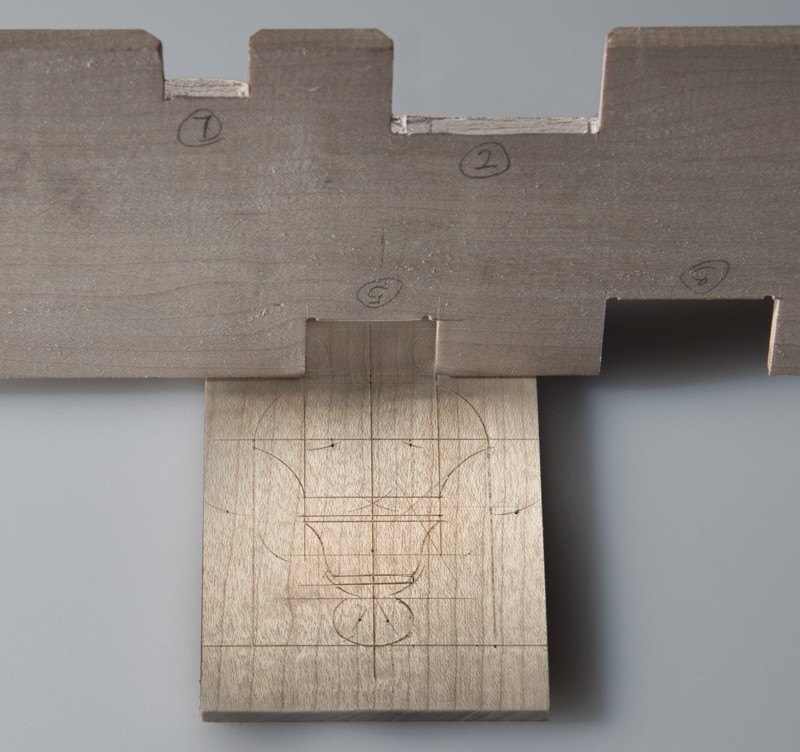
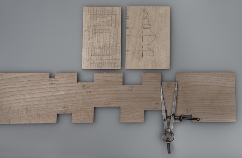
Designing the Vine Carving and Cartouche
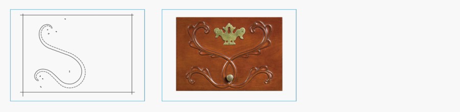
Carved appliques and ornaments typically have small, complex details that are difficult to convey in illustrations that are less than full-scale. The vine carving design is framed by the height and width of the top center drawer opening of the upper case (figs. 30, 31). The space is divided by four and five parts, creating a grid used to develop the various circles and lines. The central crossed circles are a vesica construction. After one side of the stem was drawn, Chapin used offset pairs of compass points to make the stems taper naturalistically (fig. 32). These visually accelerating curves and the tapering width of the stems form a geometric relationship to the volute in the Ionic order (see fig. 23).
The complex design of the cartouche is also created using horizontal divisions and compass constructions based on the pediment height and modules (figs. 33, 34). Chapin used offset compass points in this design to form the tapering pointed leaf tips. As seen in the vine design, using angled construction lines creates a more dynamic effect, and he developed an asymmetrical design that disguises the underlying geometric constructions.
Intrinsic Evidence of Chapin’s Design Process
The pediment of the high chest illustrated in figure 3 has paired knife lines on the section of cornice molding extending across the front of the case (fig. 35), and each pair is identical to the other in spacing and in distance from the center plinth. Although their significance was not initially apparent, these lines relate to the layout and positioning of the pediment molding and lattice panel (fig. 20). The top corners of the upper case are an area of complex layout and fitting. The side returns of the cornice are worked as a single unit including the top ogee element. The front and scroll molding match them, but the upper ogee element of the former is missing. These three elements had to be brought together to form the miters at the corners. The bottom part of the pediment molding is cut away, leaving a flat surface with only the ogee element remaining at the outer corner. This joins with the front molding to match the side return moldings. Together, the flat at the bottom edge and miter at the end determine the location of the pediment molding. Errors in these joints would affect both the height of the scroll molding and its distance from the centerline. If the location of the volute is incorrect, the pattern for the curves of the lattice panel will not join the scroll and central plinth correctly.
The paired knife lines correspond to the side-to-side locations of the scroll moldings and the upward sweeping curves of the lattice panel near the center (fig. 20). These are the two critical locations determined by the joinery at the outer corners. By using the top of the case as a work surface, Chapin could lay out the flat on the bottom edge and miter location for the pediment molding relative to the lattice panel and the length of the top. The inner edge of the left and right volutes should line up with the outer knife lines seen on the front molding. Then the thin boards that would become the left and right lattice panels could be laid on the top of the case, meeting in the middle. The inner knife lines on the cornice would be transferred to these boards so that the pattern for the latticework could be positioned correctly. Any small adjustments could be made in the short upward curve to the plinth, and the tracings show evidence of this.
The largest discrepancy between the theoretical model for Chapin’s design and the two high chests is in the height of their upper cases. The theoretical design calls for 40", but the upper cases of the chests are 39.683" and 39.47". It seems unlikely that Chapin would have chosen a height of 71 11/16" or 71 1/2" as the basis for his design because these dimensions would have been difficult to scale and divide using the nine modules of the Ionic order. The upper case drawer openings provide a possible answer to this discrepancy. On the high chest illustrated in figure 2, the drawer openings are from bottom to top: 7 31/32", 7", 5 15/16", 4 31/32", and 6 31/32". This suggests that the openings were graduated using a one-inch increment, making the intended sizes 8", 7", 6", 5", and 7", with the top row repeating the size of the second opening. The first opening equals the module used for this high chest.
The high chest illustrated in figure 3 reveals a slightly different approach. The upper case drawer rails are 13/16" thick, even though the lower case rails are 7/8" as on the other example. From bottom to top the openings are: 8 1/4", 7 1/8", 5 15/16", 4 7/8", and 7 1/16". If these drawer openings were graduated using a 1 1/8" increment, the intended sizes appear to be 8 1/4", 7 1/8", 6, 4 7/8", and 7 1/8", with the top row repeating the second opening as seen in the first high chest.
The drawer layout of both chests would align more closely with the theoretical model if the bottom board (or boards) of their upper cases were equal to the thickness of the waist molding. On the high chest illustrated in figure 2, using the corrected drawer progression, the five drawer openings total 33". The front cornice molding is 1 3/4" high, making the total 34 3/4". If the intended height was 40", the remaining 5 1/4" would be divided between the six rails, making their thickness 7/8", which is their measured thickness. On the high chest illustrated in figure 3, using the corrected drawer progression, the five drawer openings total 33.375". The cornice molding is 1 3/4", making the total 35.125". If the intended height was 40", the remaining 4.875" would be divided between the six rails, equaling 13/16", which is their measured thickness. This suggests that the rail thickness on this chest was adjusted to accommodate the difference in the drawer progression. If that example had lower case rails that were also 13/16" thick, the discrepancy would appear to be more of an arbitrary choice. But both drawer progressions combine with their six rails and cornice to total the expected 40". The errors in both cases resulted from small measuring errors in the drawer spacing and the thickness of the bottom board being less than the thickness of the waist molding.
It is possible that the thickness of the bottom boards was reduced to ensure that it was thoroughly hidden by the waist molding, but the more likely explanation for the discrepancies is that Chapin’s original design considered only the drawer openings. The drawers on both high chests are lipped and partially cover all of the rails except the bottom one. Realizing that the lipped drawers made the upper rails appear thinner, Chapin may have made the pine bottom thinner so that less of the cherry rail above was visible. This would have changed the overall height of the upper case but not the size of the carefully graduated drawer openings. For both high chests the deviation from the expected 40" total upper case height may have resulted from Chapin refining his design. The 1/4" to 5/16" loss should be considered relative to the total height. As a percentage it is a relatively small error and may have been tolerated to improve the appearance of the drawer rails.
The dimensions of the high chests also reveal a significant difference in the size of the leg blanks. On the example illustrated in figure 2, the overall width of the lower case is equal to the height of the upper case measured to the front cornice molding. On the other chest, the overall width of the lower case equals the height of the upper case measured to the true top. In both instances this creates a 1:1 ratio, but in different ways. On the high chest illustrated in figure 3, the additional thickness of the leg blanks increases the overall width, making that dimension the same as the upper case height measured to the true top. This could have been achieved by making the rails longer, but that would have required redesigning the curved pattern of the bottom front rail.
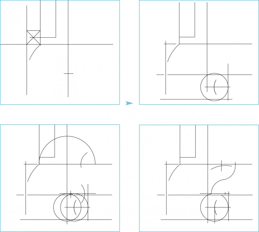
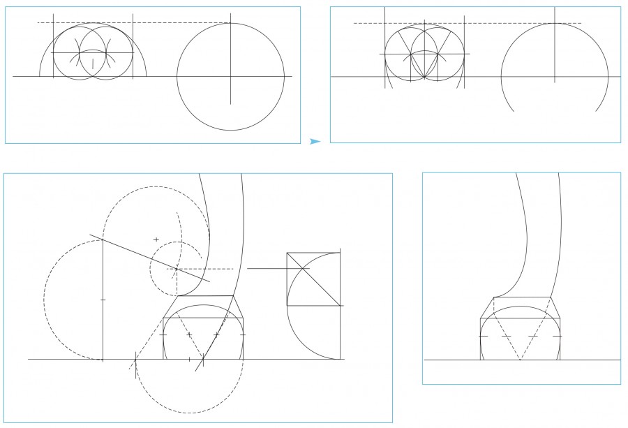
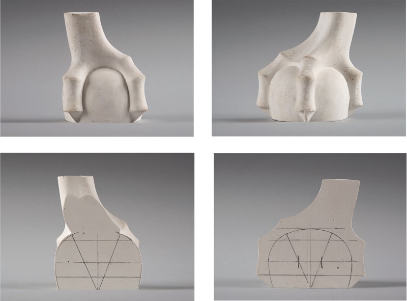
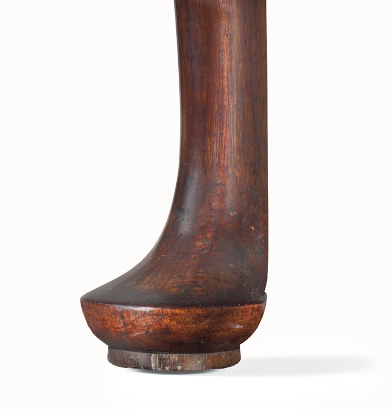
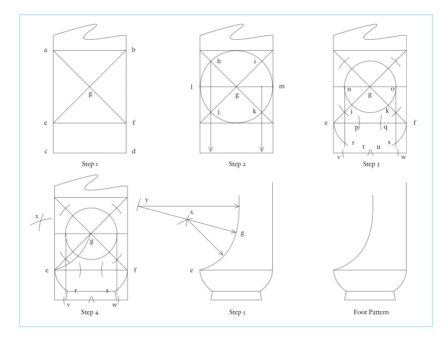
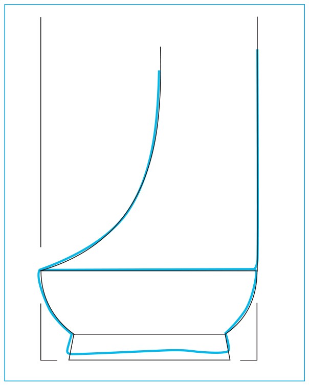
Because three-dimensionally curved elements are difficult to analyze, the authors obtained castings of the feet of the high chest illustrated in figure 3 and sawed them apart to expose sectional views. These sections located the height of maximum circumference for the ball—measured parallel to the bottom—and showed that the curves above correspond to a false ellipse construction (figs. 36, 37). Many craftsmen used geometric constructions to produce “false ellipses.” The simplest methods featured circular arcs of two radii, as illustrated and explained in Langley’s Builders Compleat Assistant (fig. 38). Chapin’s false ellipse was based on a construction of overlapping circles. As the line drawings illustrated in figure 39 demonstrate, the blank size is divided into three parts to give the radius of the two overlapping circles. The top arc has a larger radius and joins the small circles smoothly. This means that the maximum diameter of the ball falls on what would be the major axis of an ellipse. The arcs that swing down to the floor from the maximum diameter use the blank size as their radius. This geometric construction is what gives the ball the appearance of being compressed. The larger feet of the high chest illustrated in figure 3 were designed to fit that object’s leg blanks, which were based on a root-2 division of the 4" radius used for the module of the overall height (4 ÷ √2 = 2.828", rounded off). The maximum diameter measured on the casting was 2.78". This degree of deviation is explained by the carving and scraping that would have occurred during construction.
A pattern for this foot would have helped the carver locate the ball on each of the four sides of the blank by showing the height and depth below the surface where the top of the ball would be exposed. Additionally the corners created by the bevels on both front sides and both rear faces would have located the knuckles on the toes. The pattern moves the top knuckle of the side toes in from the surface of the blank, allowing all of the toes to be established with saw cuts.
The preceding drawings and captions demonstrate that the entire design for a Chapin high chest can be created and rendered with compass and straight edge. The rectilinear divisions and curved elements possess the underlying ratios and proportions that satisfy the craftsman’s desire for symmetry. Dimensions determined by the radius or diameter of the various modules and dimensions based on whole-number divisions and root-2 constructions are manifest in Chapin’s design to a degree that virtually excludes coincidence. The entire design, from the initial scale drawing to the full-scale layout and pattern development, can be produced following a logical sequence of steps that is consistent with eighteenth-century architectural and furniture making practice.
The Design Process of Benjamin Frothingham
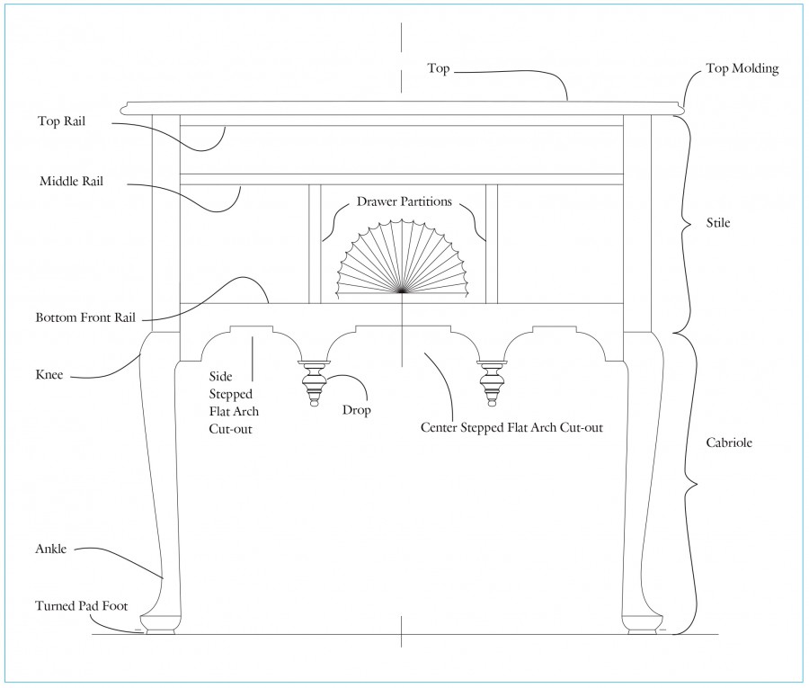
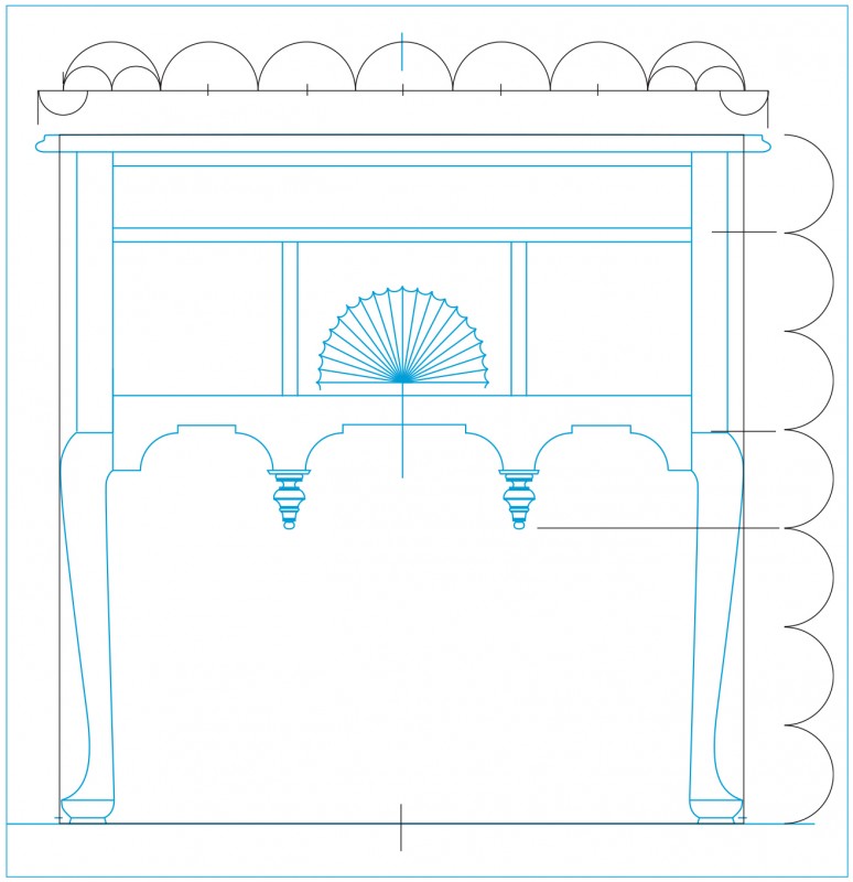
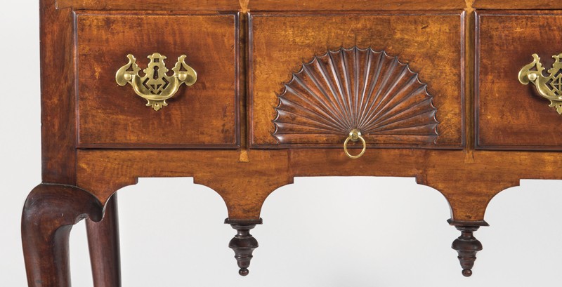
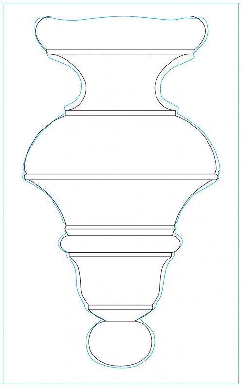
The dressing table illustrated in figure 1 is part of a suite including a matching high chest signed by Benjamin Frothingham. Frothingham’s work tends to be fairly restrained but competently made, and occasionally he used exotic woods—in the case of this high chest and dressing table, sabicu, also known as “horseflesh mahogany.” Although scholars have characterized this furniture as “unexceptional,” that term belies the complexity of Frothingham’s designs.
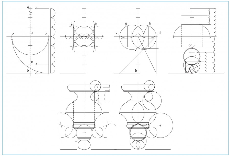
The number seven was key in the development of the dressing table’s design, suggesting Frothingham’s use of the Tuscan order. Repeatedly, given dimensions were divided into seven equal units, separated into groups of three and four, either of which might then be divided by seven again. This sequence recurs from the largest dimension to the smallest. Related to the divisions of seven is the division by multiples of seven. Many of the submodules Frothingham used to establish dimensions and locations were based on dividing the overall height or width—which are each 31 1/2"—by some multiple of seven. For example, dividing 31 1/2" by 56 equals 9/16", which is the thickness of the drawer rails and partitions. Another way this could be calculated is to take the main module of 1/7 of 31 1/2", which equals 4 1/2", and then divide that by 8, which again equals 9/16". Dividing the original number by 7 and then dividing the resulting number by 8 is the same as dividing the original number by 56.
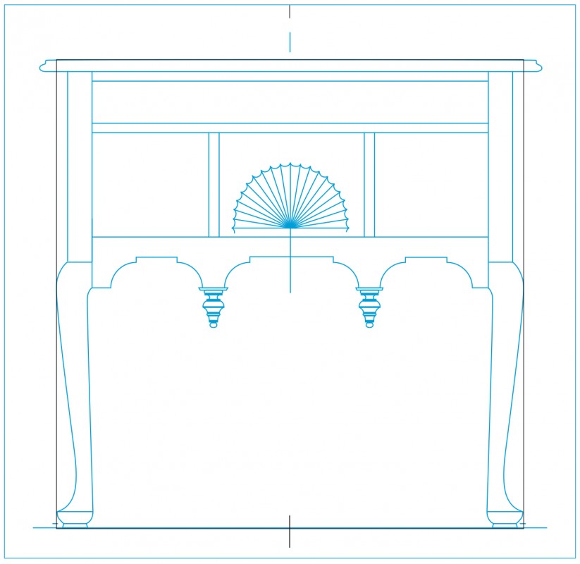
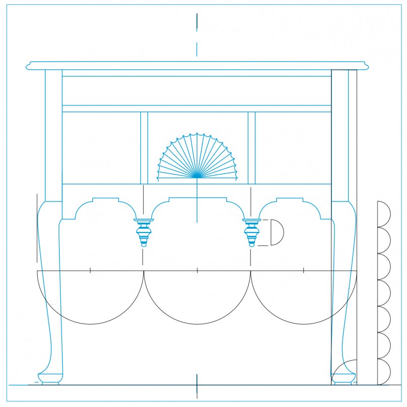
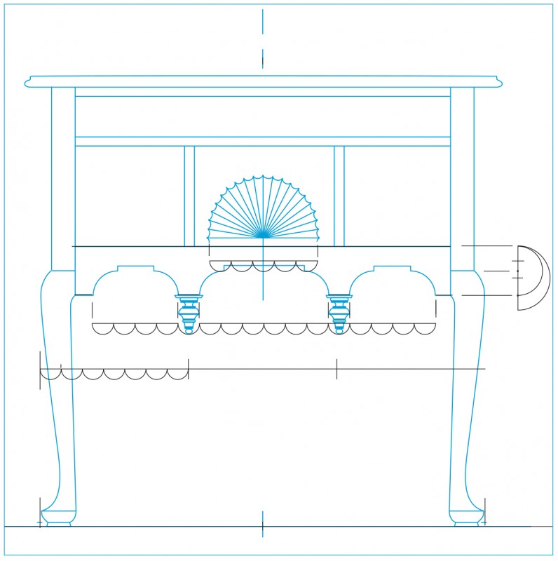
Frothingham’s starting point in the design of the dressing table was the facade dimensions. When the 31 1/2" height is divided by 7 it yields the 4 1/2" main module. Dividing that module by 72 equals 1/16". As noted in Shoemaker’s and Chapin’s designs, the number seventy-two facilitated whole-number divisions. Divisions by 1, 2, 3, 4, 6, 8, 9 produced standard increments, equal in succession: 4 1/2", 2 1/4", 1 1/2", 1 1/8", 9/16", and 1/2". The table shown on page 44 organizes all of these relationships and identifies where they were used in the dressing table’s design. The number seven and multiples of it were not the only numbers used to divide and organize space. For example, Frothingham divided the overall width of the dressing table by three to locate the centers of the vertical partitions. When his layout became primarily geometrical, as it did for the foot, he used divisions by two and the square root of two.
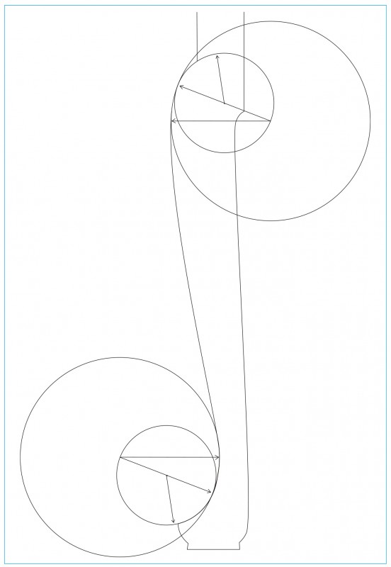
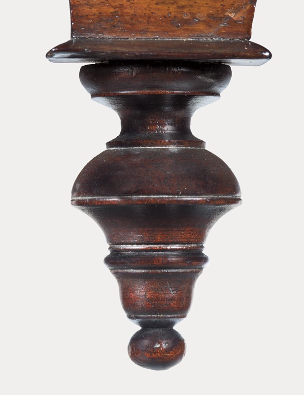
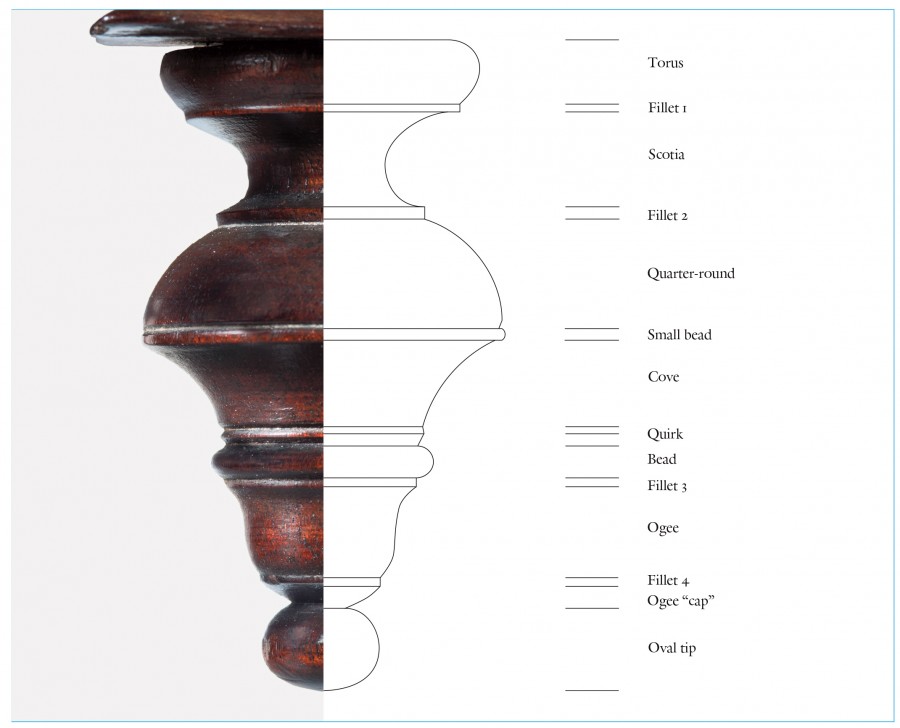
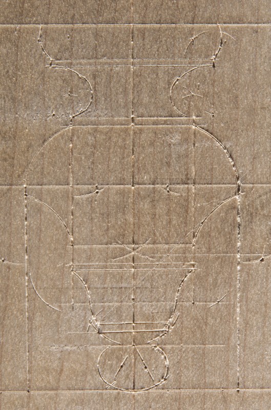
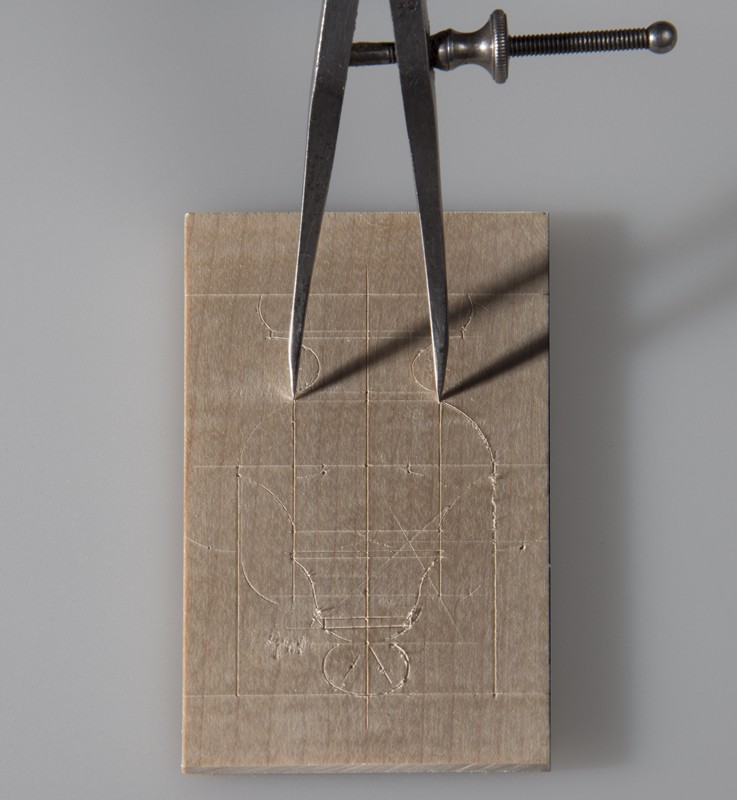
The clear arithmetical relationships of the module and submodules to standard increments of feet and inches strongly suggest that Frothingham sought to correlate standard measurements with ratios and proportions. This produced symmetry and made the transfer of dimensions from a scale drawing to a full-size layout simpler and more efficient. The drawings and photographs illustrated in figures 40-55 show the progression of Frothingham’s design, and his methodology is described in the captions. Figures 56–59 show the types of tools and implements he would have used to design the drops on the dressing table and regulate their production.
As the aforementioned illustrations reveal, Frothingham’s use of geometric constructions, ratios, and proportions can be found in virtually every aspect of his dressing table’s design. The use of seven and its multiples is so pervasive it precludes occurrence by chance. As shown in the analysis of Chapin’s design, Frothingham’s development of ratios and proportional relationships also relates to those used in classical architecture and those described in eighteenth-century architectural treatises and furniture design books.
Conclusion
This research project has explored the connections between eighteenth-century publications on furniture and architectural design and furniture from that period. The initial goal was to answer the fundamental question: how were these objects designed and built? The response published here comes from the perspective of two formally trained cabinetmakers. When looking at a piece of furniture, cabinetmakers typically think of the process used in its construction. Without a plan there are no boards to be planed or dovetails to be cut. In trying to understand how Shoemaker, Chapin, and Frothingham developed their designs, other questions with broader implications arose. Can understanding the design process and its sources facilitate attribution or help make distinctions regarding period and region? Did individual design strategies remain constant, or did they occasionally change to accommodate shifts in style?
Architectural and furniture design books and instructional treatises were directed towards builders, furniture makers, and their patrons. Virtually all of those publications attach importance to the use of geometry and proportion for design. In his Director, Chippendale states that “if no one drawing should singly answer the gentleman’s taste, there will yet be found a variety of hints sufficient to construct a new one.” In his published designs, these “hints” include scales for divisions of space and compass points with dotted lines to indicate geometric constructions for curved patterns.[13]
The use of geometry is easiest to prove through the study of curved elements. The proposed construction can be drawn full-scale and compared either to the work itself or to a tracing. If the information matches, it provides strong evidence of the geometric method. Conclusions are further bolstered if the same, or related, constructions can be found in earlier or contemporaneous publications. Any proposed constructions should also take into account the maker’s tolerances of workmanship. Tracings from the left and right sides of the shaped lower rail of the high chest illustrated in figure 24 reveal that the two sides deviate no more than the width of a thick pencil line except for two small areas about an inch and a half long. In both cases the irregularities interrupt an otherwise fair curve, which indicates an error in sawing or shaping. A swell in the curve on one side could have been contoured to make the shape fair, but a low spot would have required reshaping on both sides, disrupting the curve for a greater distance. The latter appears to have been the case on the Chapin high chest. Conversely, Frothingham’s drops reveal that he maintained remarkable control while working at a very small scale. The ability to design at such a minute level, to make patterns and turning gauges, and to translate that design into turned form provides further evidence of the use of geometric constructions and demonstrates the variety of curved forms that can be drawn with a compass.
The degree to which a proposed geometric construction conforms to a tracing of the work can be evaluated by measuring the discrepancies. The attempt to recreate the sequence of steps used to develop a construction is less easily proven. Tracings cannot tell which parts of the curves came first, and it is possible that more than one sequence of steps can be used to develop the same design. In these cases one would evaluate the logic and simplicity of the steps required. The lower rail of the Chapin high chest illustrates this point. Initially one might expect the drawing to have started either at the outside corner or on the centerline, but it appears to have begun with the cusp, which falls on the two diagonal lines (fig. 25). This would have been unlikely had Chapin begun working from either end. It is important to remember that the proposed sequence of steps can be rejected without invalidating the claim that the curves were compass-generated. It is always possible that the same construction of circles could be generated using a different sequence.
In a design, proportional relationships are harder to prove because they are abstract. Even if a designer intended to establish proportional relationships in his work, those relationships could be obscured by inaccurate workmanship. Pieces of furniture that exhibit high standards of workmanship are, therefore, easier to evaluate.
The methodology used in this project could be applied to a wide range of topics. Studying the work of a single maker with a documented chronology of forms might determine if the drafting strategies used by that craftsman changed over time. John Townsend, whose work is often signed and occasionally dated, would be an excellent candidate. Similarly, comparing the work of Eliphalet Chapin to furniture from Philadelphia and Windsor, Connecticut, might help identify the source of his design and drafting strategies.
In The Work of Many Hands: Card Tables in Federal America 1790–1820, Benjamin Hewitt, Patricia Kane, and Gerald Ward examined 265 card tables and recorded twenty-six shapes. A study of that large group could yield information on the use of geometric constructions from place to place. Several of the table shapes are described as featuring elliptic curves, but are they true drafted ellipses or compass constructions using multiple radii? This is just one example of the kind of work that could be done in the study of curved patterns.[14]
If a maker used an unusual geometric construction in his design, it might be helpful in making an attribution. One would want to exercise restraint, because designs could have been transferred through patterns and story poles. A craftsman might also have copied the work of another without understanding the underlying order of that object. Chapin’s journeymen continued to make furniture based on his designs in their own shops. For future research, the most important consideration is the investigation of additional examples of different forms and places of manufacture. If similar proportional relationships and constructions are identified in the work of other makers, it will suggest that design methodologies like those manifest in Chapin’s and Frothingham’s work were common in the eighteenth-century cabinetmaking trade and understood by many patrons.