


Benjamin Frothingham, dressing table, Boston, Massachusetts, 1760–1785. Sabicu and mahogany with white pine. H. 31 1/2", W. 33 3/4", D. 20 5/8". (Courtesy, Winterthur Museum; photo, Gavin Ashworth.)
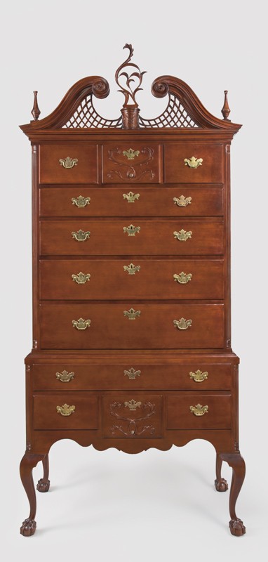
High chest of drawers, attributed to Eliphalet Chapin, East Windsor, Connecticut, 1775–1785. Cherry with white pine. H. 81", W. 38" (Courtesy, Wadsworth Atheneum: photo, Gavin Ashworth.)
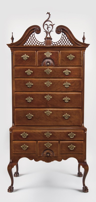
High chest of drawers, attributed to Eliphalet Chapin, East Windsor, Connecticut, 1770–1790. Cherry with white pine. H. 87 1/8", W. 40 1/4", D. 20 1/8". (Courtesy, Winterthur Museum; photo, Gavin Ashworth.)
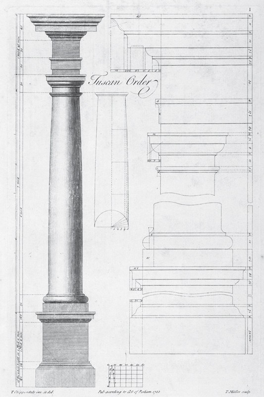
Design for the Tuscan order illustrated on pl. 1 in Thomas Chippendale’s The Gentleman and Cabinet-Maker’s Director (1754).
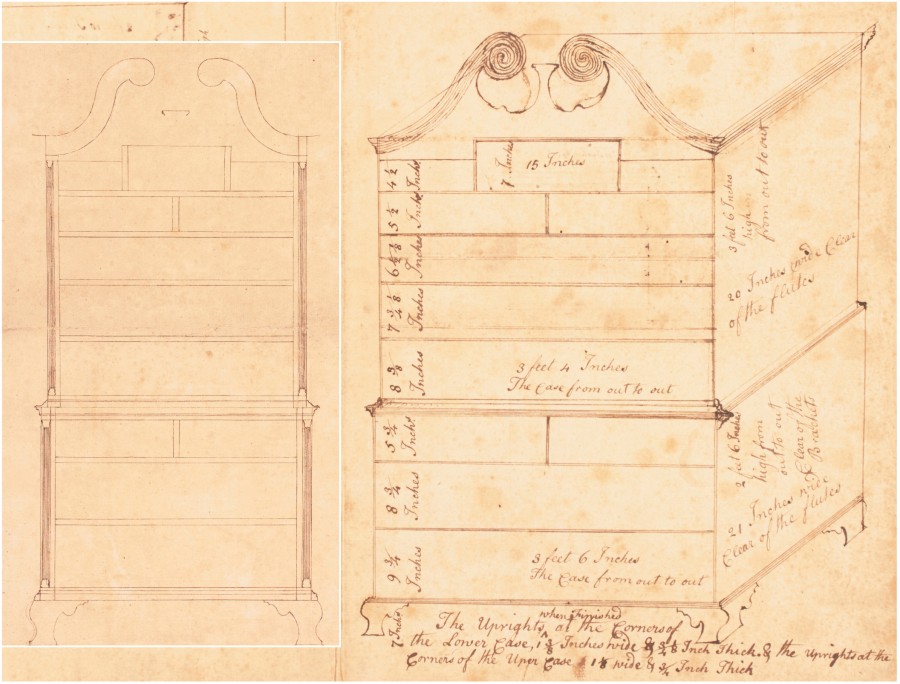
Drawing of a chest-on-chest, attributed to Jonathan Shoemaker, Philadelphia, Pennsylvania, ca. 1766. Pen and brown ink on buff laid paper. 16 9/16" x 13 1/8". (Courtesy, Philadelphia Museum of Art, gift of Walter M. Jeffords, 1950-102-1a.) Shown on top of figure 6.
Drawing of a chest-on-chest, attributed to Jonathan Shoemaker or Samuel Mickle, Philadelphia, Pennsylvania, ca. 1766. Pen and brown ink on buff laid paper. 16 9/16" x 13 1/8". (Courtesy, Philadelphia Museum of Art, gift of Walter M. Jeffords, 1950-102-1a.) Steve Brown is the first scholar to determine that this drawing and the one shown in fig. 5 refer to the same design. Shown underneath figure 5.
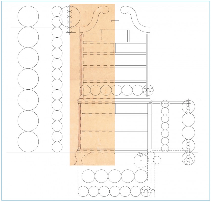
Line drawing of the chest-on-chest design illustrated in fig. 5. (Drawing, Will Neptune; artwork, Wynne Patterson.) Shown over a detail of fig. 5.
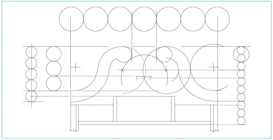
Line drawing of the upper case of the chest-on-chest design illustrated in fig. 5. (Drawing, Will Neptune; artwork, Wynne Patterson.)
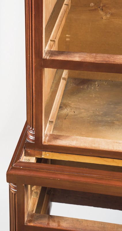
Detail of the waist molding and bottom of the upper case of the high chest illustrated in fig. 2. (Photo, Gavin Ashworth.)

Detail of the back of the high chest illustrated in fig. 2 showing the cornice molding, back, and top board. (Photo, Gavin Ashworth.)

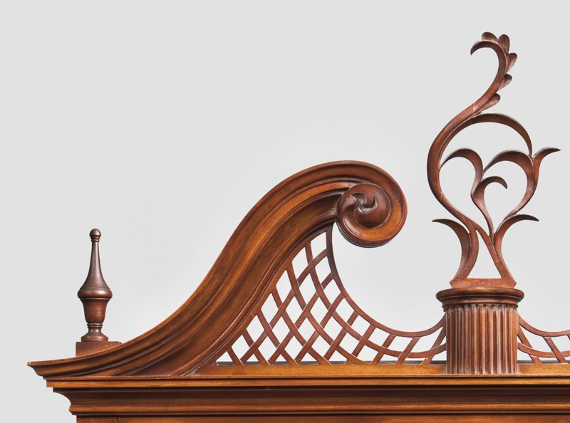
Detail of the pediment of the high chest illustrated in fig. 2. (Photo, Gavin Ashworth.)
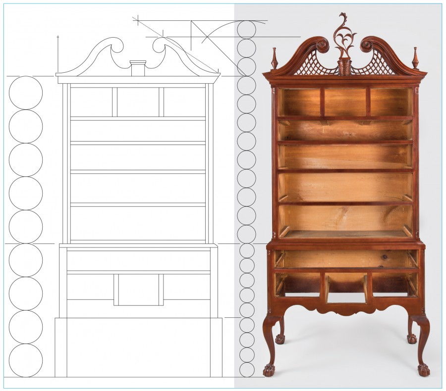
Line drawing of a Chapin high chest of drawers with a modular overlay. (Drawing, Will Neptune; artwork, Wynne Patterson.)
1. On the left side, the high chest is divided into nine 8" modules, with the upper case having five units (40") and the lower case four units (32").
2. On the right side, the height of the lower case is divided into nine new modules (32 ÷ 9 = 3.556"). From the knee to the waist molding there are five modules (17.778"), and from the floor to the knee there are four modules (14.222").
3. On the right side the height of the upper case is divided into nine new modules (40 ÷ 9 = 4.444"). One third of this height (4.444" x 3 = 13.333") is added above the upper case to establish the rake line of the pediment.
4. The height of the three modules is divided by swinging an arc through a diagonal line. This is a division by the √2 (13.333" ÷ √2 = 9.428", rounded). A line at this height crosses the rake line to determine the height of the pediment and the location of the highest point (13.333" ÷ √2 = 9.428", rounded).

Line drawing of the lower case of a Chapin high chest of drawers with a modular overlay. (Drawing, Will Neptune; artwork, Wynne Patterson.)
1. On the left side are the four 8" modules of the lower case height (4 x 8 = 32").
2. This height is divided into nine new modules, with the floor to knee height four modules (4 x 3.556 = 14.222") and the knee to waist molding five modules. (5 x 3.556 = 17.778").
3. The 3.556" module is divided into four parts. Three of these are the width of the leg blank (2.667"), two are the stile thickness (1.778").
4. Across the bottom, five of the 8" modules give the overall width of the lower case, which equals the height of the upper case (8 x 5 = 40").
5. At bottom center, two quarter circles of the 8" module have squares drawn around them and arcs swing the diagonal length down on each side. These are multiplication by √2 and locate the centerlines of the partitions that divide the bottom rail into three drawer openings (4 x √2 = 5.657 5.657 x 2 = 11.314").
6. The stile is divided into seven parts. The center of the fourth unit locates the middle rail.
7. Inside the lower case, the height is divided into three and four parts. The center of the one-third circle locates the cutout in the rail for the center drawer. The bottom fourth circle is the width of the bottom rail on the sides.
8. The two small circles across the upper case left side transfer the leg stile thickness to the upper case.
9. Above the upper case, the 8" module is subdivided into eight parts; one of these is the width of the quarter column (shown as a circle). This size is transferred down to the lower case leg stile to mark the quarter column.
10. The lower case module was divided into four parts in step number three. One of these parts gives the thickness of the waist molding, top divider, and middle divider (marked by circles).
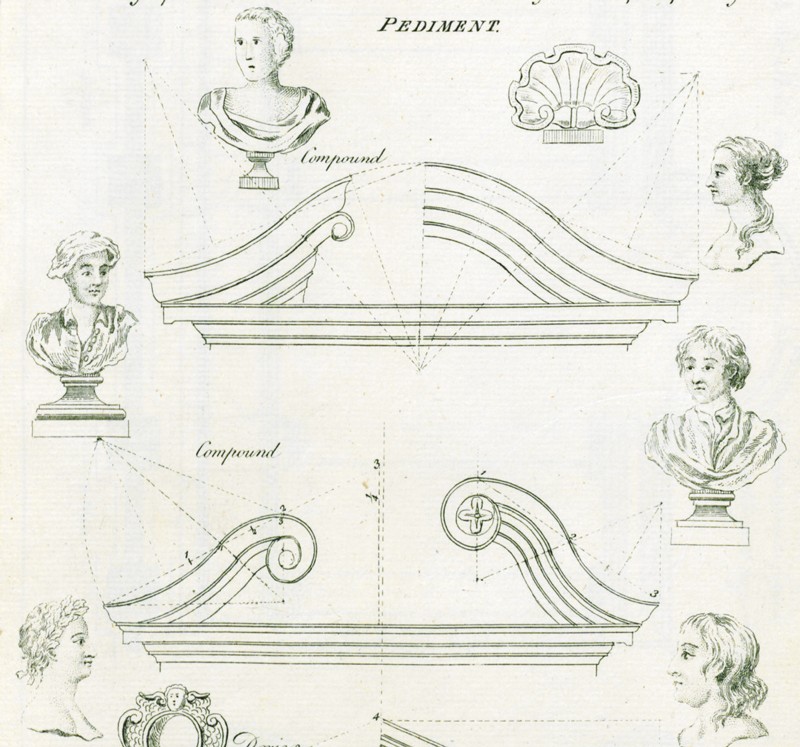
Detail of a compound pediment illustrated on pl. 12 in William Pain’s The Builder’s Companion, and Workman’s General Assistant (1758), p. 45.
Detail of the left side of the pediment of the high chest illustrated in fig. 3. (Photo, Gavin Ashworth.)
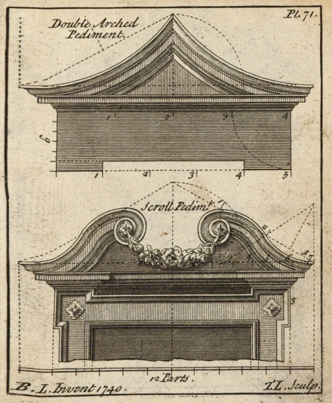
Design for a scroll pediment illustrated on pl. 71 in Batty Langley and Thomas Langley’s The Builder’s Jewel (1751).
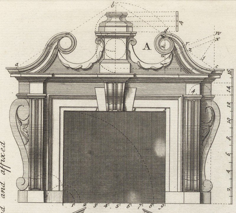
Design for a pediment illustrated on pl. 68, fig. A, in Batty Langley and Thomas Langley’s The City and Country Builder’s and Workman’s Treasury of Designs (1741).
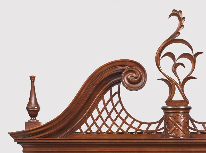
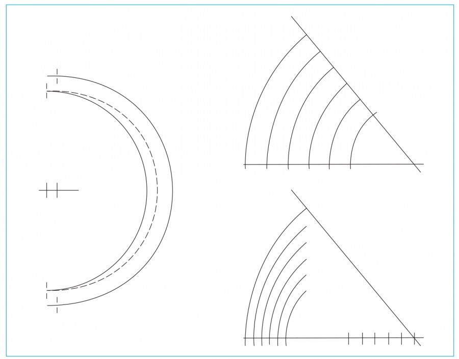
Line drawings showing the development of a Chapin pediment and tympanum. (Drawing, Will Neptune; artwork, Wynne Patterson.
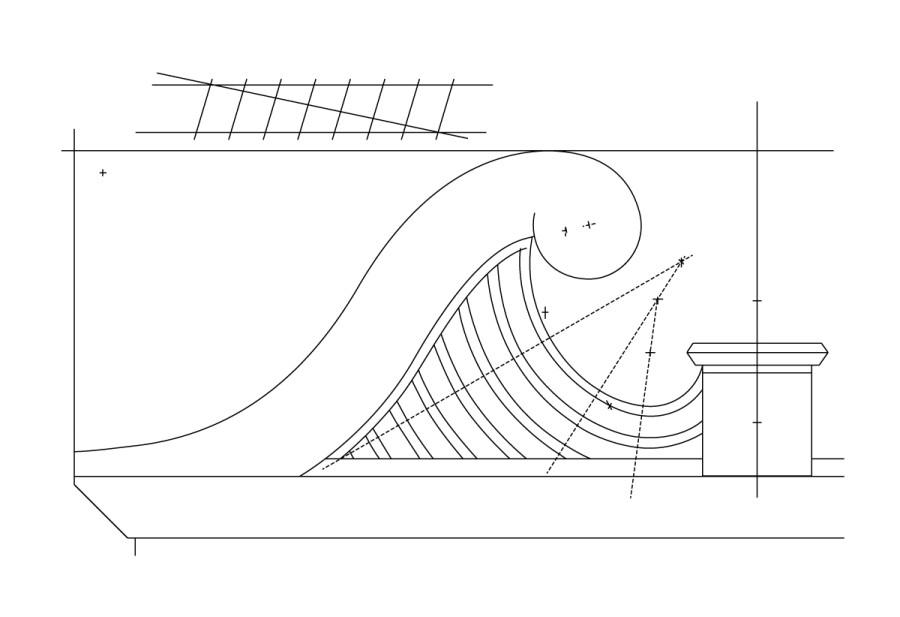
Line drawings showing lattice elements and compass points related to the pediment molding pattern. (Drawing, Will Neptune; artwork, Wynne Patterson.) The straight section is between the parallel dotted lines.
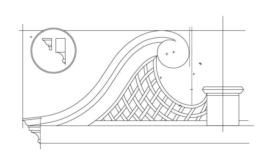
Line drawing showing completed lattice pattern combining the two previous layouts. (Drawing, Will Neptune; artwork, Wynne Patterson.)
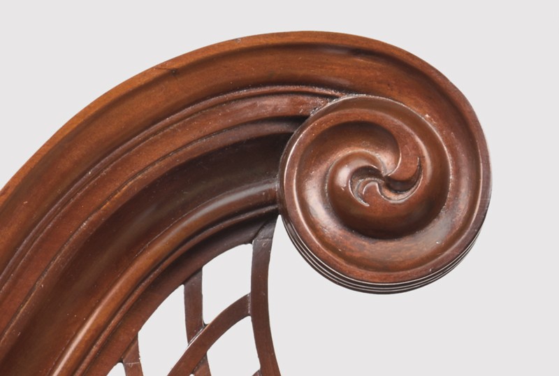
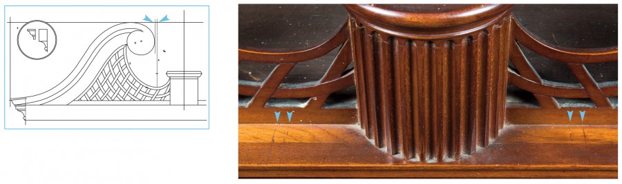
Detail of the left scroll molding and volute on the high chest illustrated in fig. 2. (Photo, Gavin Ashworth.)
Line drawings of volute geometry and leafage. (Drawing, Will Neptune; artwork, Wynne Patterson.)
Detail of an Ionic volute illustrated on pl. 12, figure H, in Batty Langley’s The Builders Compleat Assistant (1738), vol. 2.
Detail of the lower case of the high chest illustrated in fig. 2. (Photo, Gavin Ashworth.)

Line drawings showing the development of the lower rail pattern used for the high chest illustrated in fig. 2. (Drawing, Will Neptune; artwork, Wynne Patterson.)
This drawing shows the completed design with the six compass points used in the construction. The central cusp falls on the diagonal line. The partitions and center drawer opening are drawn to show how the pattern uses the diagonal lines to “cradle” the center drawer.
Details of a cabriole leg on the high chest illustrated in fig. 2. (Photo, Gavin Ashworth.)
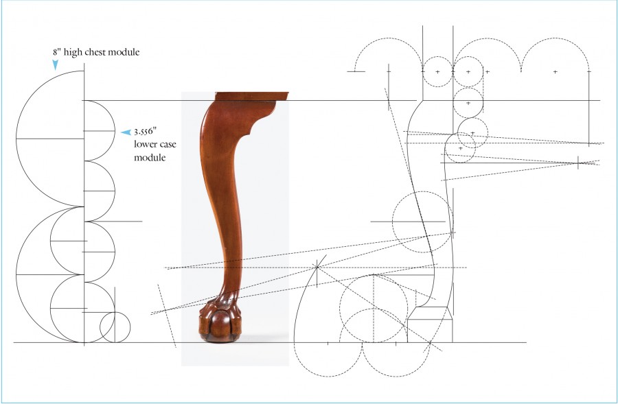
Line drawing showing the development of a cabriole leg pattern on the high chest illustrated in fig. 2. (Drawing, Will Neptune; artwork, Wynne Patterson.)
Line drawings showing the development of a knee, transition block, and quarter-column plinth on the high chest illustrated in fig. 2. (Drawing, Will Neptune; artwork, Wynne Patterson.)
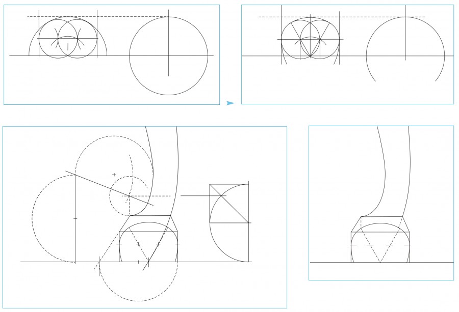
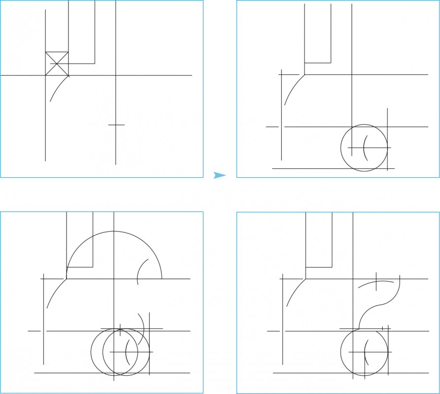
Line drawings showing the development of a ball and claw foot on the high chest illustrated in figs. 2, 26. (Drawing, Will Neptune; artwork, Wynne Patterson.)

Detail of the top center drawer of the high chest illustrated in fig. 2. (Photo, Gavin Ashworth.)
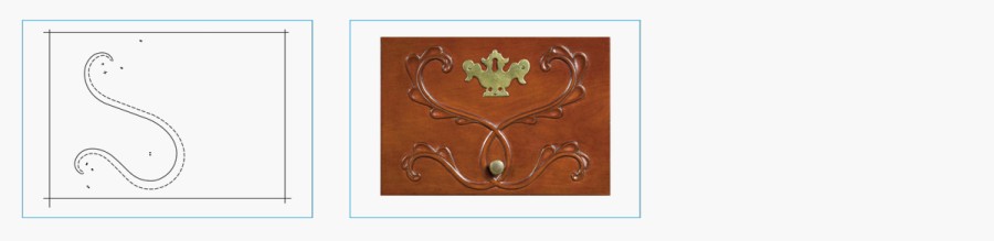
Line drawings showing the development of the applique on the top center drawer of the high chest illustrated in fig. 2. (Drawing, Will Neptune; artwork, Wynne Patterson.) The drawings show layout lines and compass points for one edge of vine carving.
Line drawing showing the drafting of tapered curved elements using off-set compass points. (Drawing, Will Neptune; artwork, Wynne Patterson.

Detail of the cartouche of the high chest of drawers illustrated in fig. 3. (Courtesy, Winterthur Museum.)

Line drawings showing the development of the cartouche on the high chest illustrated in fig. 3. (Drawing, Will Neptune; artwork, Wynne Patterson.)
Detail showing the knife marks on the cornice molding of the high chest of drawers illustrated in fig. 3. (Photo, Gavin Ashworth.)
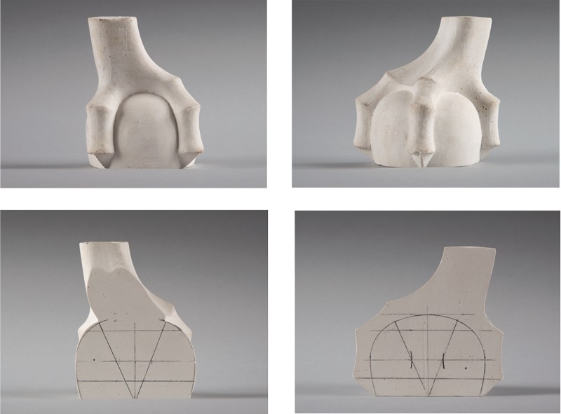
Plaster casts of a foot on the high chest of drawers illustrated in fig. 3, showing false ellipse construction on the sectional views. (Photo, Gavin Ashworth.)

Plaster casts of a foot on the high chest of drawers illustrated in fig. 3. (Photo, Gavin Ashworth.) The half castings are overlapped, with the front one showing the shape of the ball against the half foot illustrated in fig. 36, with a pencil line of the drafted shape following edge of ball.
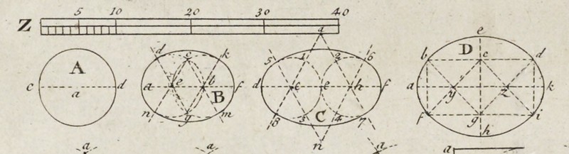
False ellipse constructions illustrated on pl. 4, in Batty Langley’s The Builders Compleat Assistant, 1st ed. (1738 ), vol. 2.
Line drawings showing the development of the ball and claw foot on the high chest of drawers illustrated in fig. 3, showing false ellipse section. (Drawing, Will Neptune; artwork, Wynne Patterson.)
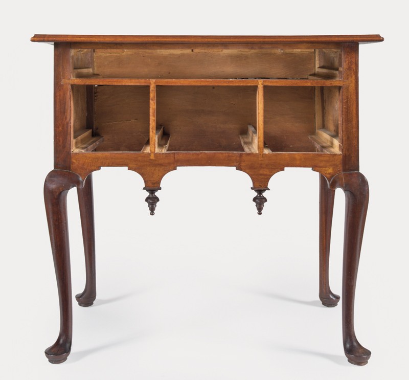
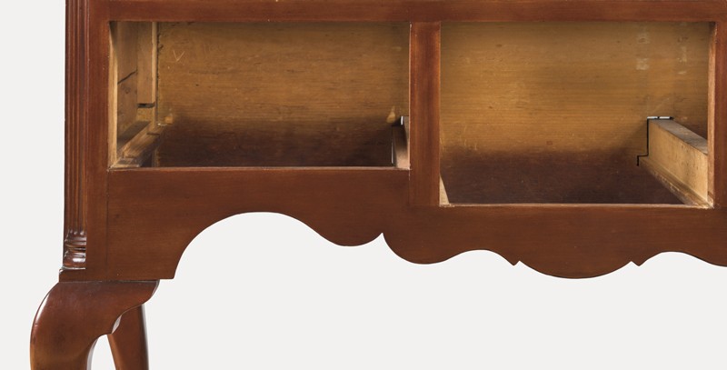
Front view of the dressing table illustrated in fig. 1 with drawers removed. (Photo, Gavin Ashworth.)
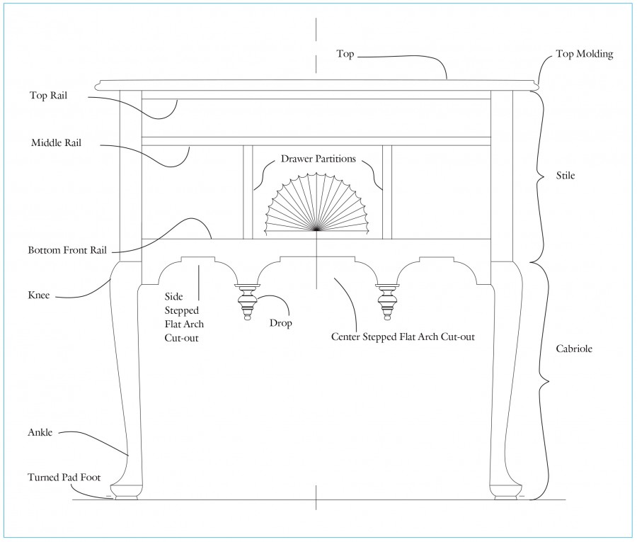
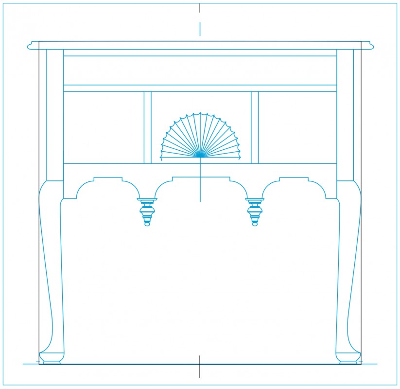
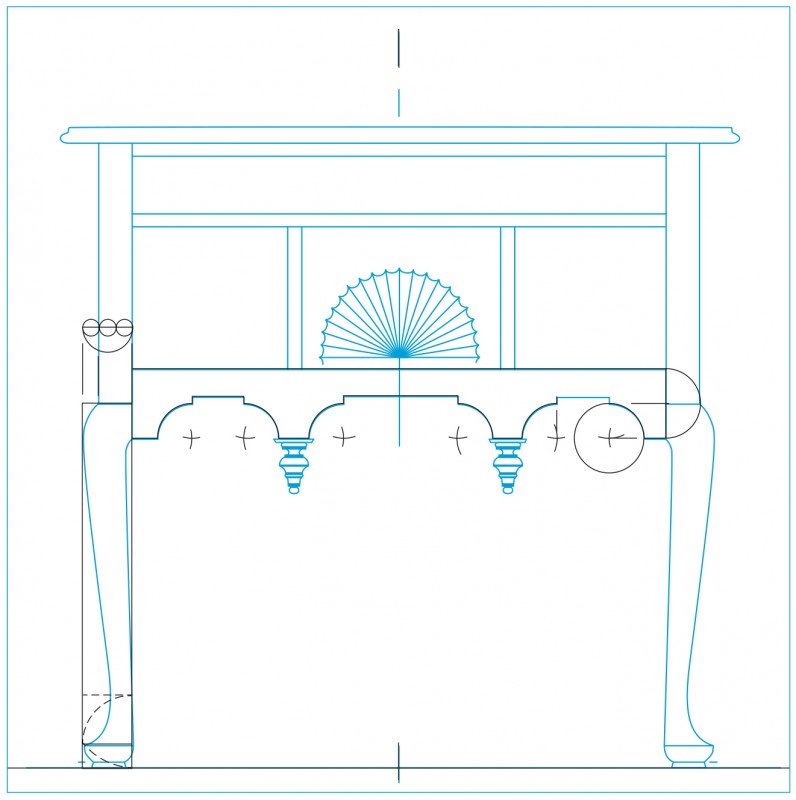
Line drawing of the dressing table illustrated in fig. 1 with various components and features designated. (Drawing, Steve Brown; artwork, Wynne Patterson.)
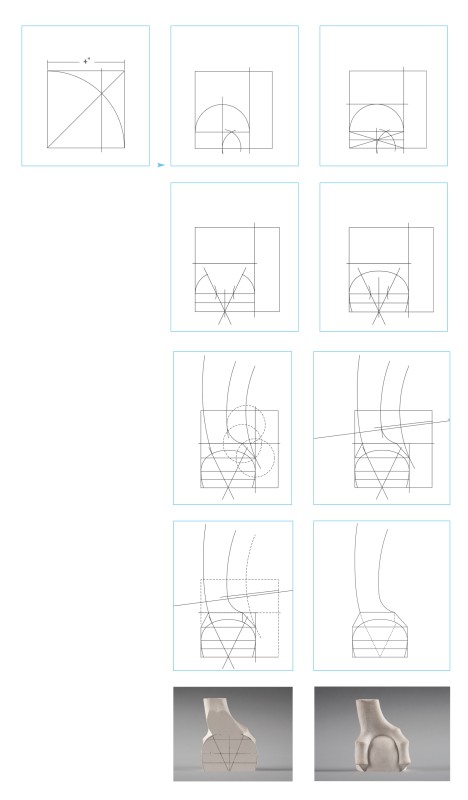
Line drawing of the dressing table illustrated in fig. 1 with a square overlay. (Drawing, Steve Brown; artwork, Wynne Patterson.) Frothingham’s design began with a square (a 1:1 ratio), which is typical in classical design. The height and width are 31 1/2" measured from the floor to the top and from the widest point of the legs.
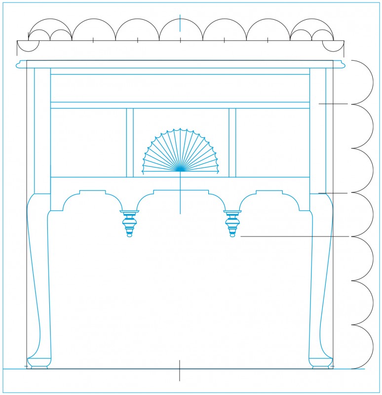
Line drawing of the dressing table illustrated in fig. 1 with a modular overlay. (Drawing, Steve Brown; artwork, Wynne Patterson.) The height and width are divided into seven equal units or “modules.” Each module measures 4 1/2". Subsequent smaller modules will be referred to as “submodules” and described in relation to the 4 1/2" module. Each of the seven horizontal modules is divided by 2, dividing the overall width by fourteen submodules, each measuring 2 1/4". The length of the top is equal to fifteen of these submodules and is centered according to the case. The top length measures 33 3/4", which relates to the width of 31 1/2" as a 15:14 ratio. The vertical module divisions locate key elevations. One module down from the top locates the center of the drawer divider thickness; three locate the top of the cabriole leg and the center of the bottom rail; and four locate the elevation of the bottom tip of the drop.
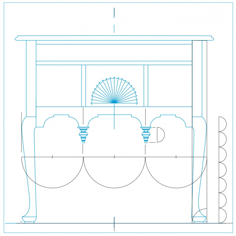
Line drawing of the dressing table illustrated in fig. 1 with an overlay showing 1/3 divisions and leg submodules. (Drawing, Steve Brown; artwork, Wynne Patterson.) The width is divided into three equal parts, each 10 1/2". These divisions locate vertical lines that run through the centers of both the drops and the vertical drawer partitions. The height of the leg is divided vertically into seven equal parts. The actual measurement is an irrational number, but it rounds off to only 0.009" larger than 2 2/16", representing an acceptable approximation. This measurement is the leg blank thickness and the length of the drop.
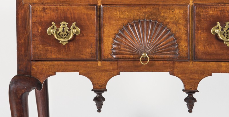
Detail showing the carved fan, shaped lower rail, and drops of the dressing table illustrated in fig. 1. (Photo, Gavin Ashworth.)
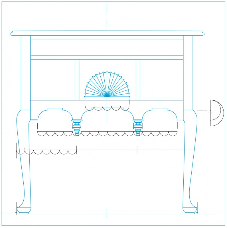
Line drawing of the dressing table illustrated in fig. 1 with an overlay showing the fan, front rail, and stepped arch cut-out submodules. (Drawing, Steve Brown; artwork, Wynne Patterson.) To the side of the knee, a 4 1/2" main module is reduced to three quarters of its size to define the lower rail width. This new submodule measures 3 3/8" and is centered at the same elevation as the top of the leg. Frothingham divided each of the one-thirds by 7. This created twenty-one submodules dividing the overall width. Each submodule measures 1 1/2". These submodules are added together to determine several different dimensions. The remaining flats of the bottom rail edge directly above the finials equal one submodule. The width of each outer arch is equal to four submodules totaling 6"; the width of the middle arch equals six submodules totaling 9"; and the diameter of the carved fan is five submodules totaling 7 1/2". This can be seen as an arithmetic progression running from 4-5-6-7 and possibly 8 if the two one-unit flats (above the drop) are added to the middle cut-out space.
Line drawing of the dressing table illustrated in fig. 1 with an overlay showing the development of the stepped arch and modular overlay for the stiles and projection of the knees. (Drawing, Steve Brown; artwork, Wynne Patterson.) The quarter circles forming the arches are drawn using a compass set to a radius of exactly one-half of the rail width. The center for each arc lies on the line of the bottom edge of the rail and is one radius away from the end of each stepped arch. The center of each arc defines the location of the vertical 5/16" steps. The dotted lines at the bottom of the leg indicate a root-2 rectangle based on the leg blank width. Above the knee, the submodule for the leg blank is divided by 3. This determines the inner two-thirds as the stile width and the remainder as the projection of the knee.

Line drawing of the dressing table illustrated in fig. 1 showing the case and legs in blank form. (Drawing, Steve Brown; artwork, Wynne Patterson.) The top thickness is 3/4". This is one-sixth of the main module and equals the overall height (31 1/2") divided by 42, a multiple of 7. The drawer dividers and partitions are 9/16". This is one-eighth of the main module and equals 31 1/2" divided by 56, another multiple of 7.
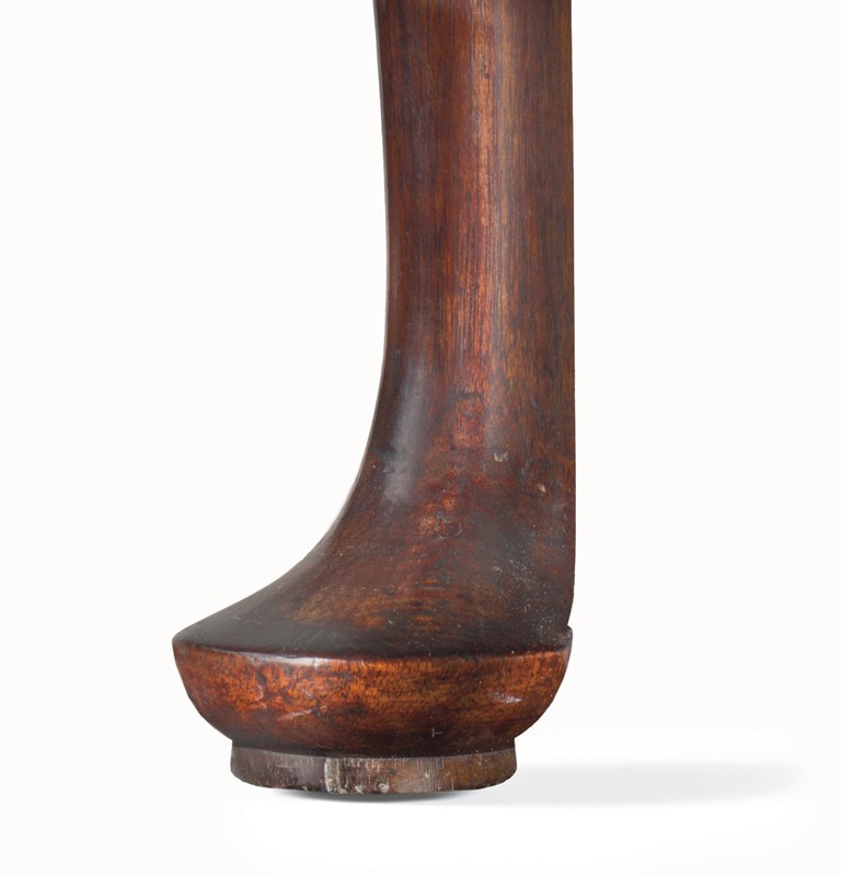
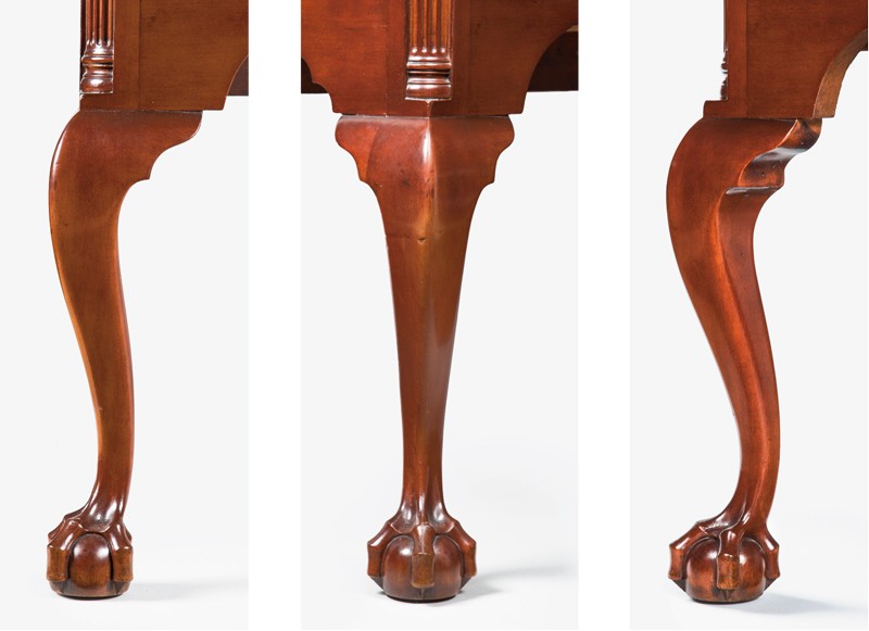
Detail of the foot and ankle of a leg on the dressing table illustrated in fig. 1. (Photo, Gavin Ashworth.)
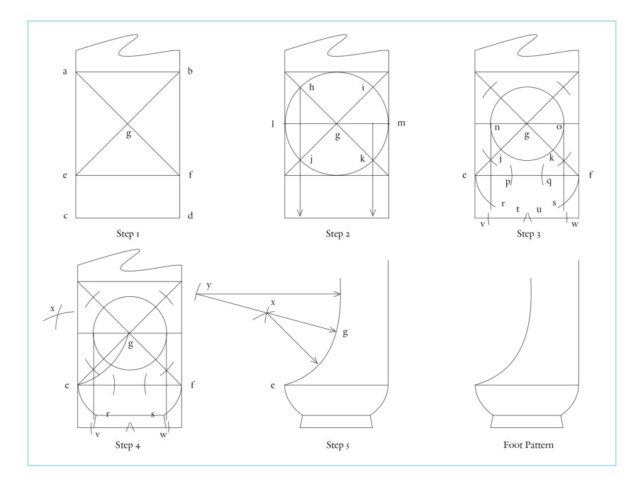
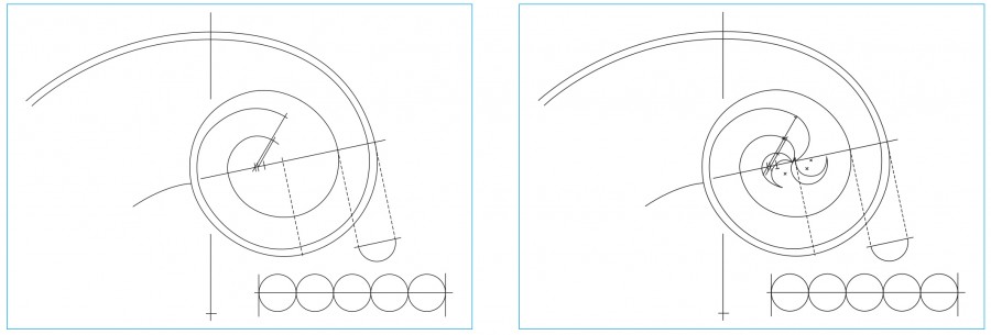
Line drawings showing the stages of foot development for the dressing table illustrated in fig. 1. (Drawing, Steve Brown; artwork, Wynne Patterson.) The geometric construction of Frothingham’s foot is described below:
1. At the bottom of the cabriole leg blank, draw a root-2 rectangle (a,b,c,d) using the width of the blank as the base of the rectangle. Divide the rectangle into the square (a,b,e,f) at the top of the rectangle with the remaining rectangle (e,f,c,d) at the bottom. This lower remainder defines the height and diameter of the foot. Draw the square’s diagonals to find center (g).
2. Using (g) as a center point, inscribe a circle (this circle represents the plan view of the full diameter of the pad foot within the leg blank). Points (h,i,j,k) result where the circle intersects with the diagonals. Draw line (h,j) and extend it to the bottom of the blank. Draw diameter (l,m) horizontally to form point (n).
3. Use (g) as the center point and line (n,g) as the radius for a smaller circle. Draw a vertical line down from point (o) to the bottom of the blank. Using points (e and f) as center points, draw small arcs that intersect line (e,f) to form points (p and q). With the compass still set to radius (n,g), and using (p and q) as centers, draw arcs (e,r and f,s). From points (r and s) use radius (n,g) to find points (t and u) on the baseline. Then do the same using (t and u) to find points (v and w).
4. Draw lines (r,s and r,v and s,w) to define bottom of foot and top of pad. Set compass to (e,g) and use this radius from points (e and g) to intersect at point (x). Use (x) as the center to swing arc with same radius from (e to g), which forms the first part of the curve from the “toe” towards the ankle.
5. Run a line from (g) through point (x) so that (y, g) equals 2 times (x,g). Set the compass to (y,g) and draw the arc from (g) to continue up past vertical to form the ankle.
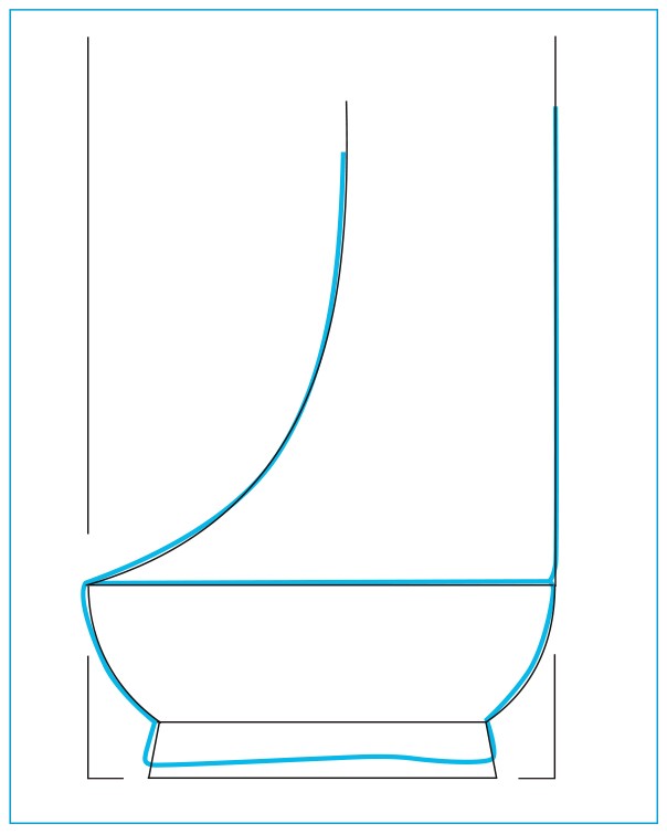
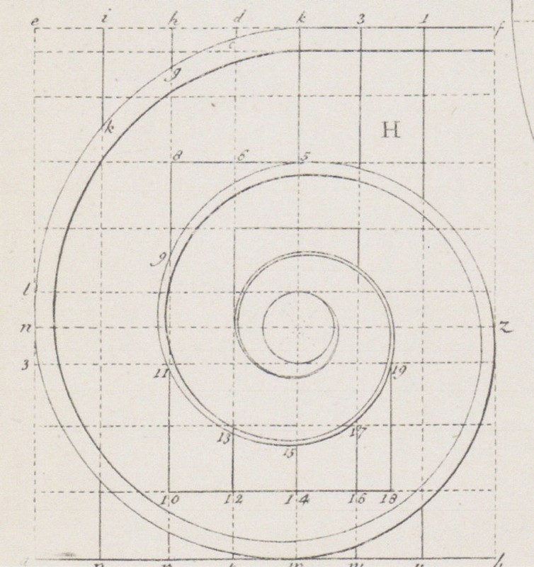
Tracing of a foot casting in blue taken from the dressing table illustrated in fig. 1 with an overlay showing the geometric development. All of the arcs or circles in this construction are related to each other by a factor of 2 or the square root of 2. Based on scribed tracings of the legs, the best match for the curve of the knee is the same combination of arcs that form the top of the foot and the ankle. (Drawing, Steve Brown; artwork, Wynne Patterson.)
The two radii that form the curve from the tip of the foot up to the vertical part of the ankle also were used to draw the curve of the cabriole leg knee from the stile down to just past vertical. Theoretically the “S-curve” of the front edge of the cabriole leg pattern could rotated 180 degrees and look the same. At the time of this writing, the complete development of the knee design remained unclear. (Drawing, Steve Brown; artwork, Wynne Patterson.)
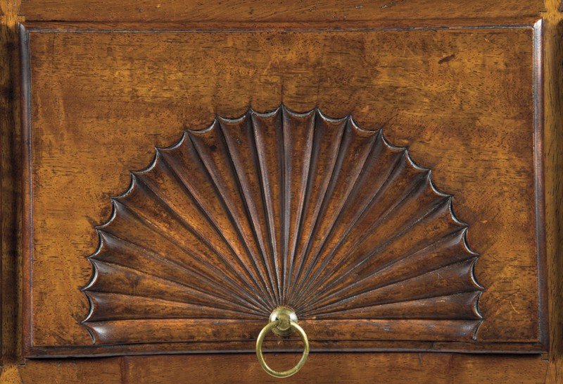
Detail of the carved fan on the dressing table illustrated in fig. 1. (Photo, Gavin Ashworth.) The carved fan provides compelling evidence of the use of 7 by its division into 20 whole and two half lobes, adding up to 21, a multiple of 7. This is a clear concrete expression of a multiple of 7 not dependent on measurement.
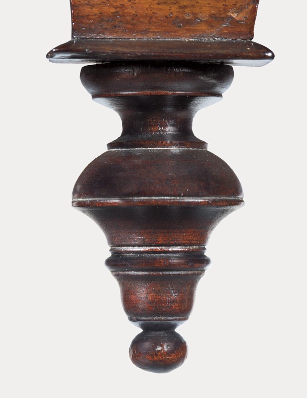
Detail of a drop on the dressing table illustrated in fig. 1. (Photo, Gavin Ashworth.) In order to decipher the design scheme, Steve Brown traced a split casting of the drop with a sharp pencil and drew elevation lines connecting one side to the other. The tracing was then checked for accuracy using vernier calipers. Of the eleven elevations measured, the lower eight diameters measured within 1/16 of an inch from one drop to the other, except for one dimension that differed by 1/32". This is remarkably precise work since turning involves cutting the profile on the surface of a revolving piece of wood. Any depth of cut the turner makes is doubled. For example, an error of 1/16" in depth changes the diameter by 1/8". In the case of these drops, the turner was controlling his depth of cut within 1/128". It is difficult to see how this degree of consistency and precision was achieved. Inconsistencies in the top three elevations suggest that the turner made a mistake and had to adjust the upper torus, fillet, and scotia. The scotia is an ideal place to transition from the error to the intended design. The measurements of the fillet at the bottom of the scotia on each drop are equal. Presumably the drop with the larger diameters is the one done correctly.
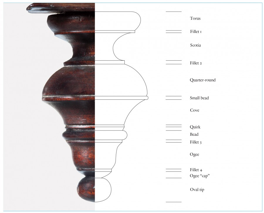
Line drawing of a drop on the dressing table illustrated in fig. 1 with labels. (Drawing, Steve Brown; artwork, Wynne Patterson.)
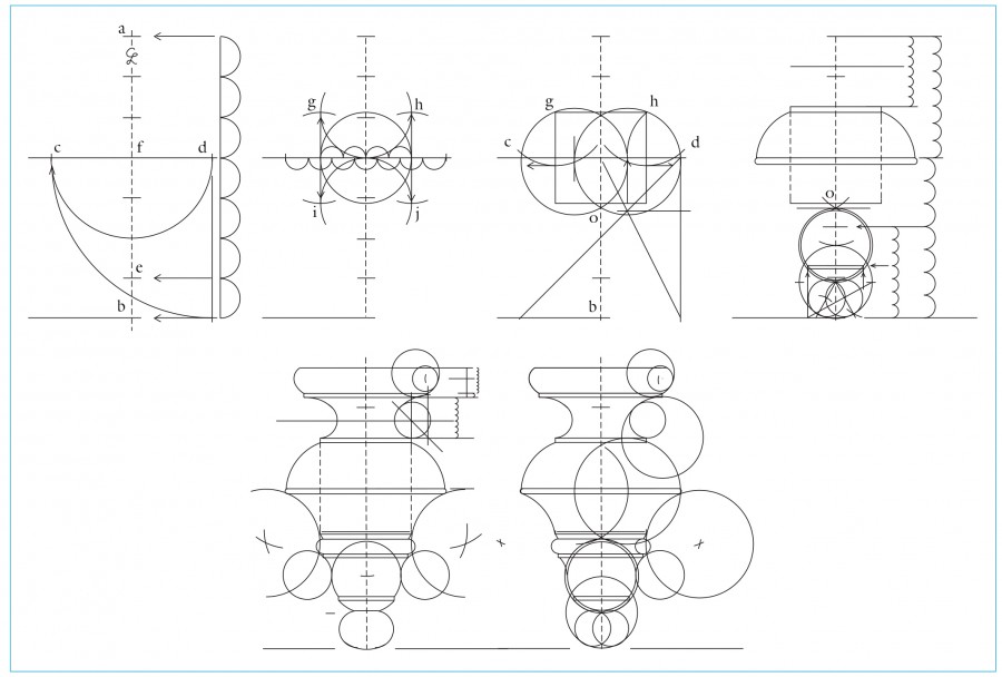
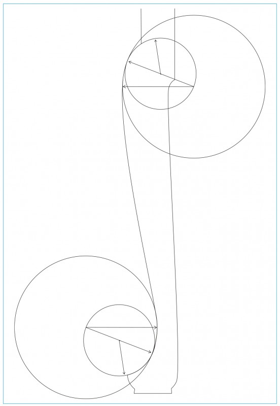
Line drawings showing the stages of drop development for the dressing table illustrated in fig. 1. (Drawing, Steve Brown; artwork, Wynne Patterson.) The geometric construction of Frothingham’s drop is described below:
1. Start with a height of 2 9/16" (the leg blank submodule) and divide evenly by 7. The overall diameter is equal to four of these seven submodules. The elevation of this diameter is four submodules up from the bottom. The height of the oval tip is one submodule.
2. Divide this diameter into seven submodules. The square’s (g,h,i,j) height and width are each equal to four of these submodules. The center of the square is point (f), and the top and bottom of the square are parallel to diameter (c,d). Points (g,h) define the bottom corners of fillet-2.
3. Divide the diameter (c,d) by 3 to draw a vesica pisces construction. This construction is defined as two overlapping circles of equal size whose centers each intersect with the outside of the other circle. This establishes the first lines of the finial profile, arcs (c,g and h,d).
4. The lower intersection of the two circles defines point (o), which initiates another vesica the length of (o,b). The top circle of this vertical vesica forms the arcs of the “ogee-cap.” The lower circle establishes the bottom curve of the oval tip. The finial tip is drawn using a simple geometric oval construction. The length of the oval is created by a vesica construction whose two circles have diameters equal to the radius of the previous vesica circles. This drawing also shows the series of divisions of elevations by 7, the separation into three and four submodules, and the subsequent division by 7 of either of those lengths (these reflect the sequences used for the development of the dressing table already discussed). Lines are transferred horizontally to indicate the new elevations.
5. The final stage shows the center points of the arcs used to create the torus, scotia, cove, bead and upper part of the ogee.
6. The circles overlaid in the finial drawing show that the curves of the finial profile are developed with compass arcs from the largest to the smallest.
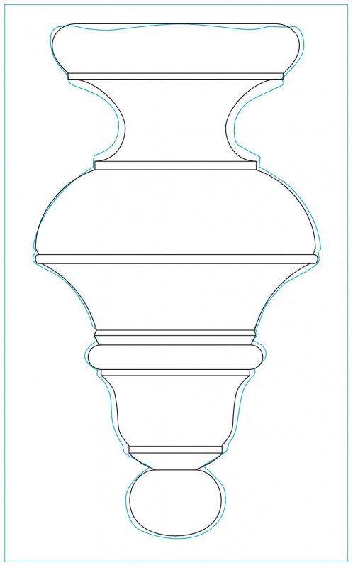
Tracing of a drop casting from the dressing table shown in figure 1 in blue overlaid with the development drawing based on geometry and ratios. (Drawing, Steve Brown; artwork, Wynne Patterson.) Because of the small size of the drop, 2 9/16", it is difficult to claim absolute certainty regarding every stage in the development of its design.
Completed design for the drops on the dressing table illustrated in fig. 1. (Photo, Gavin Ashworth.)
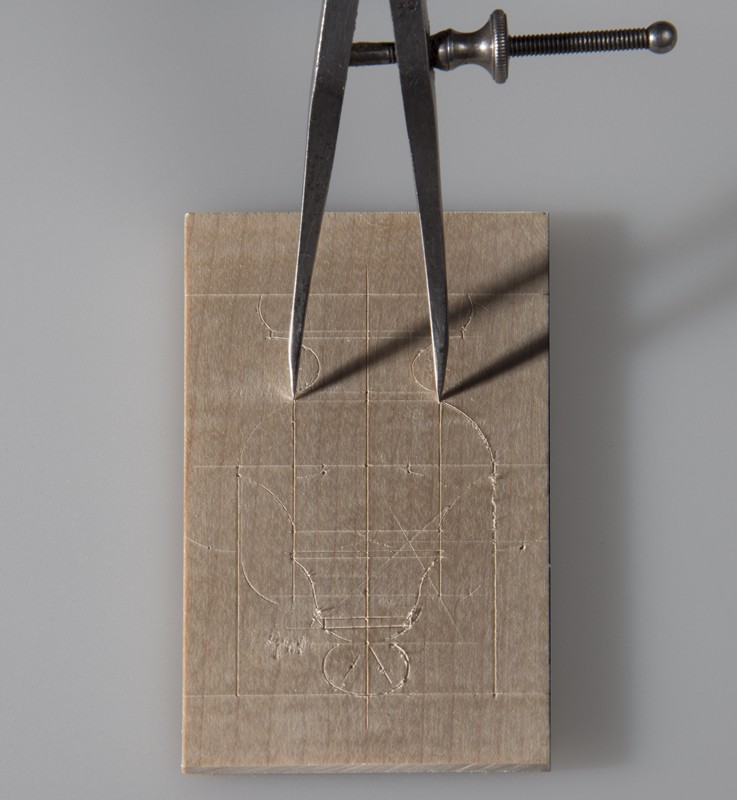
Completed design for the drops on the dressing table illustrated in fig. 1, shown with dividers. (Photo, Gavin Ashworth.) The information needed for the drop is a basic two-dimensional view showing its height, its elevations, and the diameters of the elements at each elevation. The shapes connecting the points where the elevations and diameters meet can be filled in. It would be obvious to Frothingham, his workmen, or a turner from whom piecework might have been obtained, that this profile of the drop extends from a centerline representing a three-dimensional form. All of this layout could be done with a straight edge, a knife or scratch awl, and a pair of dividers. The sample layout was done to the actual size. The elevations could then be transferred to the edge of the maple to be used as a pattern to apply them to the finial stock on the lathe.
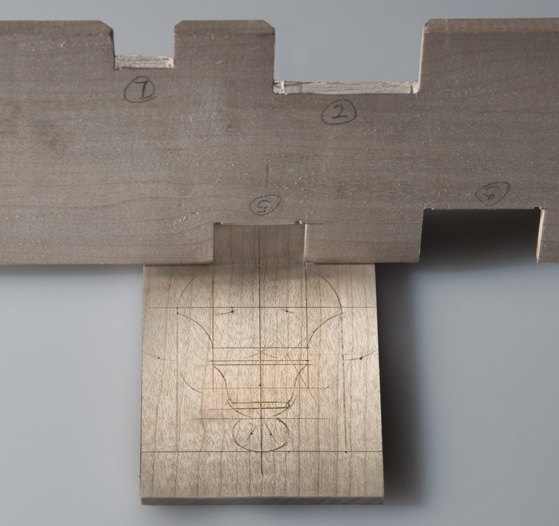
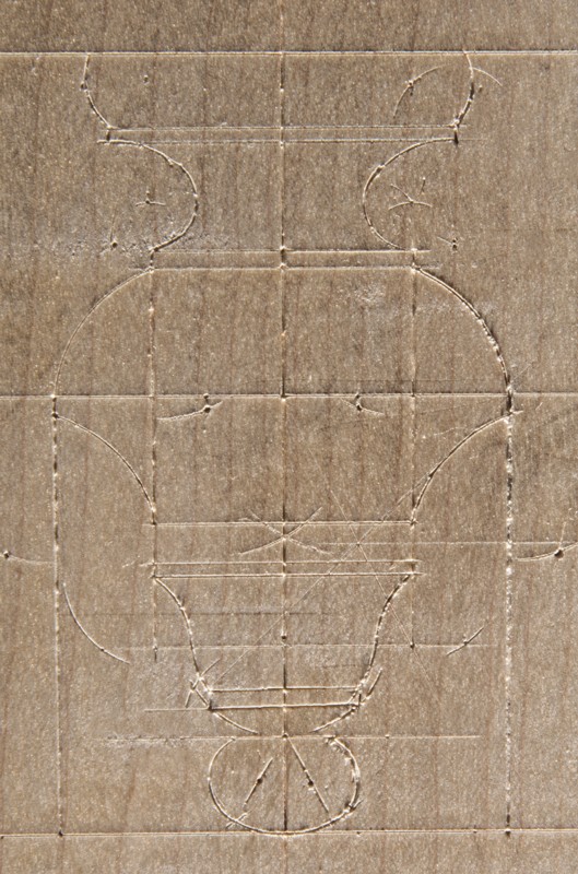
Pattern for the drops on the dressing table illustrated in fig. 1. Maple. (Photo, Gavin Ashworth.) After working out his design on paper, Frothingham likely transferred it to a wooden pattern, which would have been used to guide the turning.
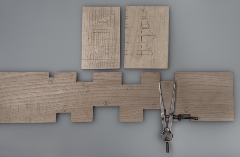
Pattern for the drops on the dressing table illustrated in fig. 1, shown with a turning gauge with notches. An accurate wooden gauge used to judge diameters is simple to make. The actual diameters are easily transferred using dividers from the layout to the gauge block. (Photo, Gavin Ashworth.)