


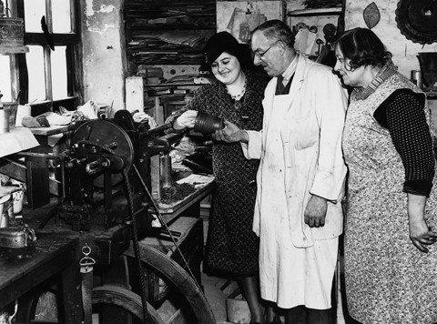
Archival photograph of the ornamental engine-turning lathe in the basalt room at the Wedgwood Etruria factory, 1941. Left to right: Mrs. Warrilow, Tom Simpson, and Mary Thornton. (Courtesy, The Warrilow Collection, Keele University Library, Newcastle-under-Lyme, Staffordshire.) In the 1950s this nineteenth-century lathe was moved to the Wedgwood Museum in Barlaston, where it is today. This photograph shows the lathe essentially as it was built; later it was highly modified.
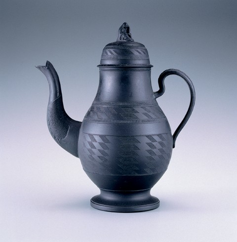
Coffee pot and cover, England, ca. 1800. Black basalt. H. 9 1/8". The engine-turned surface of this coffee pot and cover was created with the edge (rose) cam. (All objects from the Jonathan Rickard Collection unless otherwise noted; photo, Gavin Ashworth.)
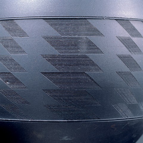
Detail of the coffee pot illustrated in fig. 2.
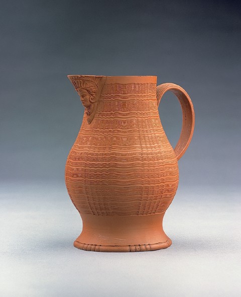
Jug, England, ca. 1775. Red stoneware. H. 7 1/2". (Photo, Jack McConnell.) The engine-turned surface of this baluster-form jug with press-molded masque snip or pouring lip was created with the end (crown) cam.
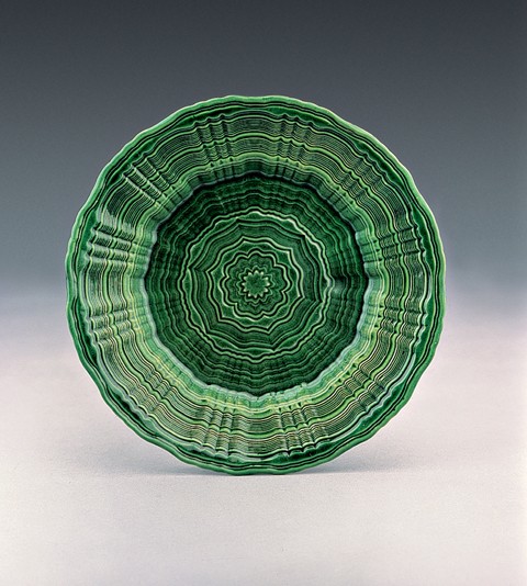
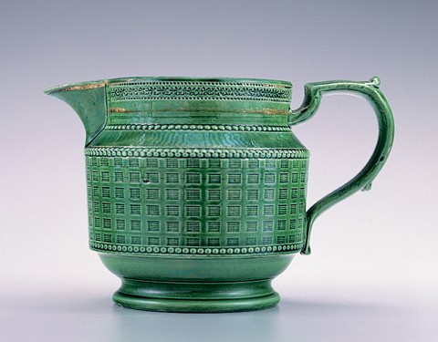
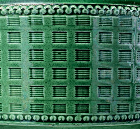
Plate, Staffordshire, ca. 1775. D. 8 3/8". (Photo, Jack McConnell.) This rare green-glazed engine-turned plate was worked on the edge cam. Wasters of engine-turned plates were among the finds at the William Greatbatch factory site in Fenton, Staffordshire.
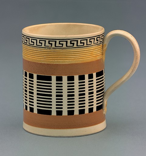
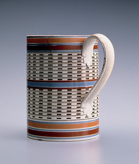
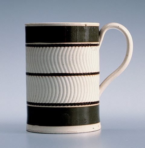
Mug, England, ca. 1800. Lead-glazed creamware. H. 3 1/2". (Photo, Jack McConnell.) The decoration at the rim of this mug with extruded strap handle with foliate terminals is rouletted and slip-filled, above a reeded band colored in the glaze with either antimony or uranium to produce the brilliant translucent yellow. The two ochre slip bands bracket a field of horizontal black slip bands cut through vertically using the edge cam.
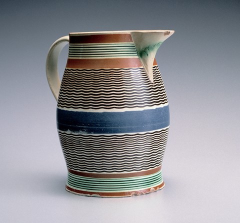
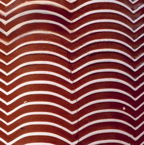
Jug, England, ca. 1790. Lead-glazed pearlware. H. 7". (Photo, Gavin Ashworth.) Baluster-form jug with slip banding, green-glazed (copper oxide brushed into the lead glaze) reeded bands brushed with a concentrated glaze mixture containing copper oxide, and black slip-filled engine-turned pattern cut using the end cam.
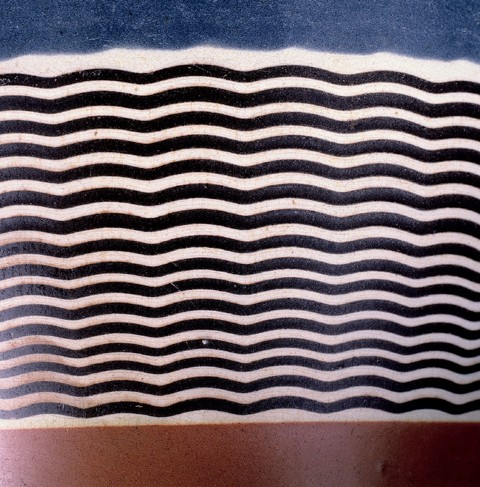
Detail of the engine-turned pattern on the jug illustrated in fig. 7
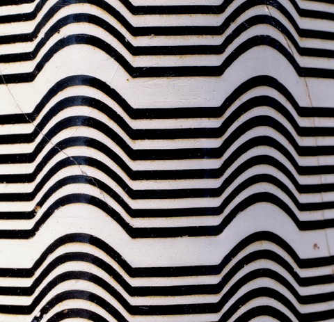
Mug, attributed to the Leeds Pottery, Yorkshire, ca. 1790. Pearlware. H. 6". (Photo, Gavin Ashworth.) Quart-capacity mug with slip banding and a black slip-filled pattern cut with the edge cam. The pattern appears in watercolor drawings in the Leeds Pottery pattern books in the Print Room of the Victoria and Albert Museum.
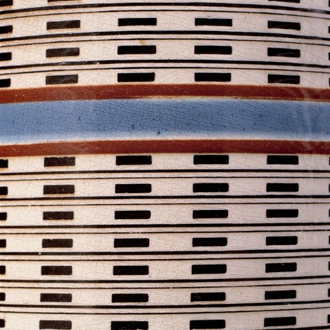
Detail of the engine-turned pattern on the mug illustrated in fig. 9.
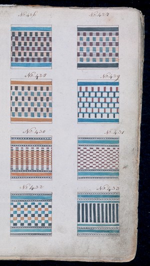
A page from the Leeds Pottery Pattern Book No. 3 showing a variety of engine-turned designs. (© V&A Images/Victoria and Albert Museum, London, www.vam.ac.uk.)
Mug, England, ca. 1800. Pearlware. H. 5 7/8". (Photo, Gavin Ashworth.) Quart-capacity mug, slip-banded with red slip-filled engine-turned decoration cut with the end cam.
Detail of the engine-turned pattern on the mug illustrated in fig. 12. The mug is shown at an angle, illustrating the trompe l’oeil effect of a faceted surface.

Mug, England, ca. 1830. Pearlware. H. 4 5/8". (Photo, Gavin Ashworth.) A pint-capacity mug with slip banding and a green-glazed reeded band with a black slip-filled engine-turned pattern cut with the end cam. Wasters of vessels with similar patterns were found in an accumulation from the James and Ralph Clews manufactory, Cobridge, Staffordshire, 1818–1834.
Detail of the engine-turned pattern on the mug illustrated in fig. 14.
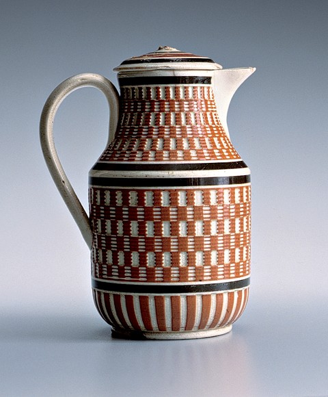
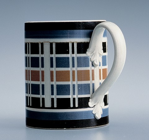
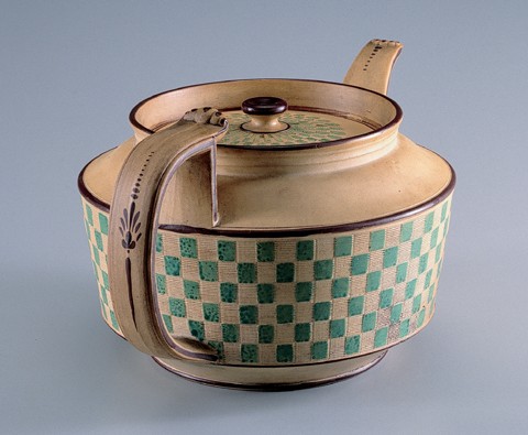
Cream jug and cover, Leeds Pottery, Yorkshire, ca. 1790. Creamware. H. 5 1/2". (Photo, Gavin Ashworth.) The engine-turned decoration cut through the slip field with a matched set of checkering cams. The extruded strap handle has foliate terminals, and the cover knop is missing. This object was found in Russia. Impressed on the bottom is “leeds pottery.” A related teapot and cover with the same mark are in the collection of the Victoria and Albert Museum.
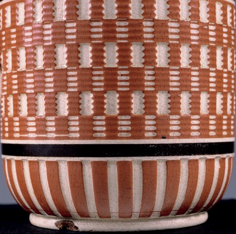
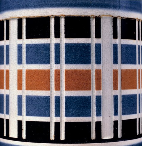
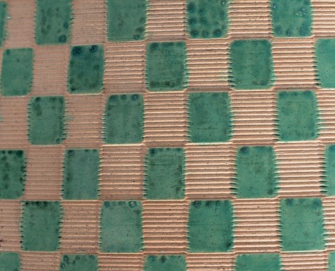
Detail of the engine-turned pattern on the jug illustrated in fig. 16.
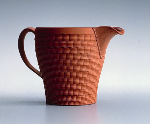
Cream jug, Wedgwood, Staffordshire, ca. 1820. Red stoneware. H. 3 1/4". (Photo, Gavin Ashworth.) The engine-turned basketweave pattern of this cream jug with glazed interior was cut using a double-edge cam. It has the impress “wedgwood” on the bottom.
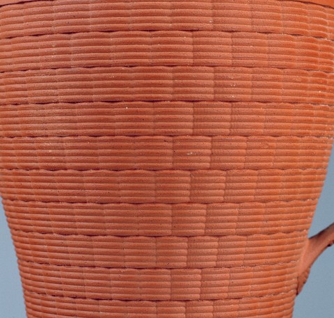
Detail of the engine-turned pattern on the cream jug illustrated in fig. 18.
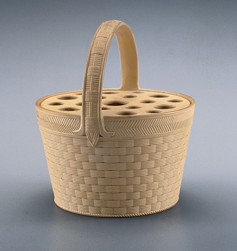
Potpourri basket, Wedgwood, Staffordshire, ca. 1810. Caneware. H. 5". (Photo, Gavin Ashworth.) The caneware body has the same engine-turned pattern as the redware creamware jug illustrated in figs. 18, 19.
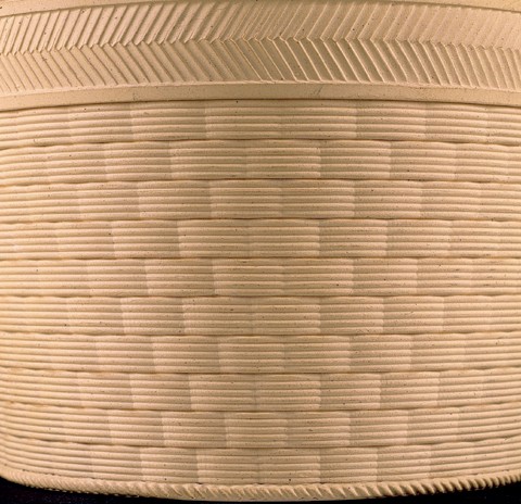
Detail of the engine-turned pattern on the basket illustrated in fig. 20.
Mug, England, ca. 1800. Pearlware. H. 3 3/4". (Photo, Gavin Ashworth.) A half-pint-capacity mug, slip-banded and cut using a standard edge cam used for vertical reeding, but with a curved blade.
Detail of the engine-turned pattern on the mug illustrated in fig. 22.
Mug, attributed to Wood & Caldwell, Burslem, Staffordshire, 1797–1818. Pearlware. H. 3 3/4". (Photo, Gavin Ashworth.) A half-pint-capacity mug, slip-banded with vertical cuts through the slip using the edge cam.
Detail of the engine-turned pattern on the mug illustrated in fig. 24.
Jug, Britain, maker unknown, ca. 1830. H. 4". (Photo, Gavin Ashworth.) A green-glazed cream jug with both rouletted and engine-turned patterns decorating the surface. Vestiges of overglaze gilding remain.
Detail of the engine-turned pattern on the jug illustrated in fig. 26.
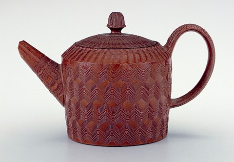
Teapot and cover, England, ca. 1790. Lead-glazed red earthenware. H. 4". (Photo, Gavin Ashworth.) The spout and vertical sides of the body were cut with the end cam, whereas the cover and the pot’s shoulder patterns required the edge cam.
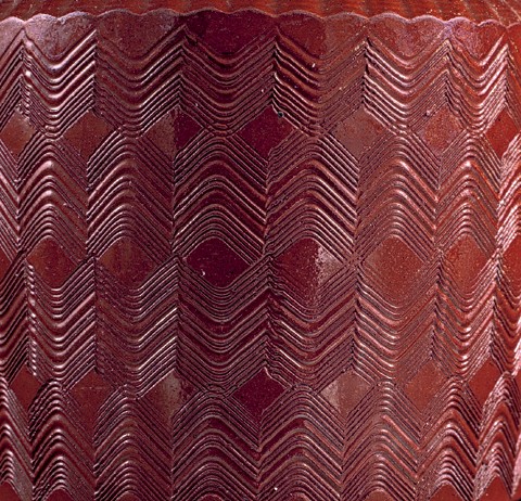
Detail of the engine-turned pattern on the teapot illustrated in fig. 28.
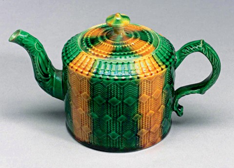
Teapot and cover, Davenport, Longport, Staffordshire, ca. 1810. Caneware. H. 4 1/2". (Photo, Gavin Ashworth.) Enamel decorated with engine-turned dicing on the body and cover, this example has the impressed mark “davenport” on the bottom.
Detail of the engine-turned pattern on the teapot illustrated in fig. 30.
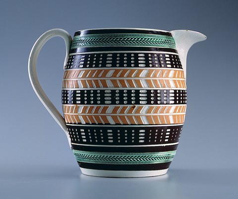
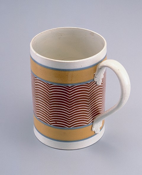
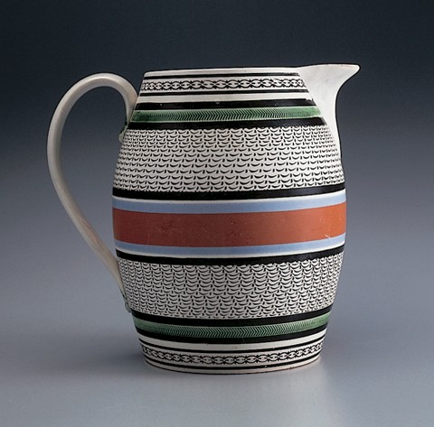
Jug, Britain, ca. 1820. Pearlware. H. 7 1/2". (Photo, Gavin Ashworth.) A barrel-form jug banded with black and ochre-colored slip, engine turned with the edge cam through the slip to reveal the white body. Green-glazed rouletted bands bracket the engine-turned surface cut with two different blades, the chevron pattern requiring a V-shaped blade.
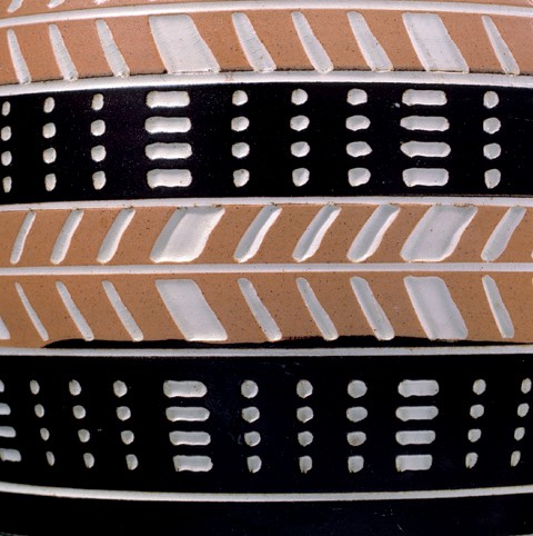
Detail of the engine-turned pattern on the jug illustrated in fig. 32.
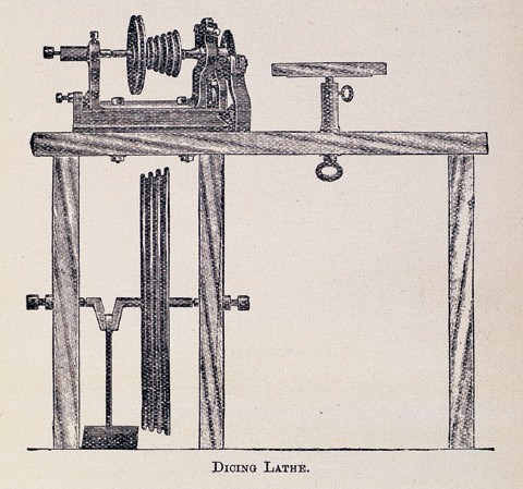
A line engraving that depicts a simple dicing lathe, reproduced in Ernest Albert Sandeman, Notes on the Manufacture of Earthenware (London: H. Virtue and Company, 1901).
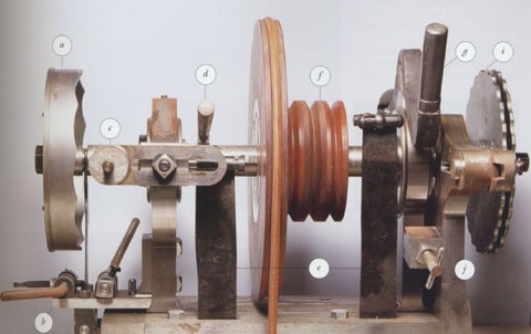
Side view of the Carpentier engine lathe showing the basic working components. (a) The crown (end) cam: left and right edges can be cut with patterns. (b) Double-action, crown-cam spring assembly: allows crown cam to be followed on left or right edge and creates spring tension for the sideways pumping action. Josiah Wedgwood describes making this addition to his redesigned lathe in a 1768 letter. (c) Crown-cam follower. (d) Lock to keep main shaft from moving sideways. (e) Main springs: put pressure against pivoting main frame as it follows the edge cams and produces a rocking motion. (f) Wooden pulleys: using a large pulley slows the motion and using a small pulley increases it. (g) Mainframe locking arm (seen in the down position): prevents the front-to-rear rocking action. (h) Spring tensioner: increases pressure on main springs, either forward or backward. (i) Edge cams: can be changed simply by removing a nut and sliding another cam on or off. Like the double-action, crown-cam spring assembly, this appears to have been invented by Wedgwood for use on his 1768 redesigned lathe. (j) Depth stop: controls the depth of cut the knives make in the body. (All demonstration photos by Gavin Ashworth.)
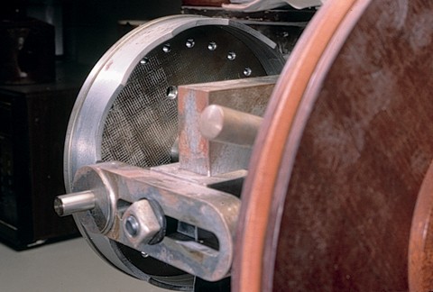
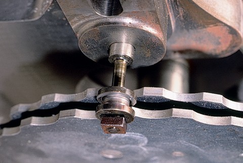
The end cam on Carpentier’s lathe. At the lower left is the follower. At right is a portion of the wooden flywheel.
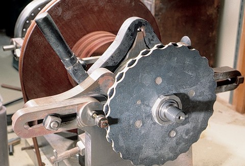
The edge cam on Carpentier’s lathe. At lower left center is the follower; the flywheel appears in the background.
Detail of the follower mounted against one of two attached edge cams used, in this configuration, to create checkered patterns. For this application, alternating patterns are cut with one of the edge cams, then the offset patterns are cut with the other.
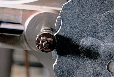
Another view of the follower and an edge cam. The follower’s size can be changed depending on the size and intricacy of the pattern needed to be run against on the edge cam.
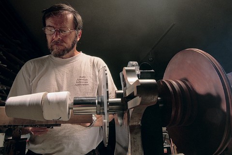
Don Carpentier at his lathe. Left to right: a leather-hard pot mounted on a plaster chum, or mandrel; the edge cam; clamp; and the wooden flywheel.
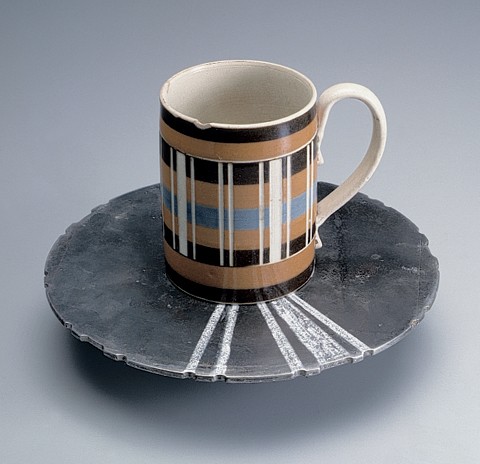
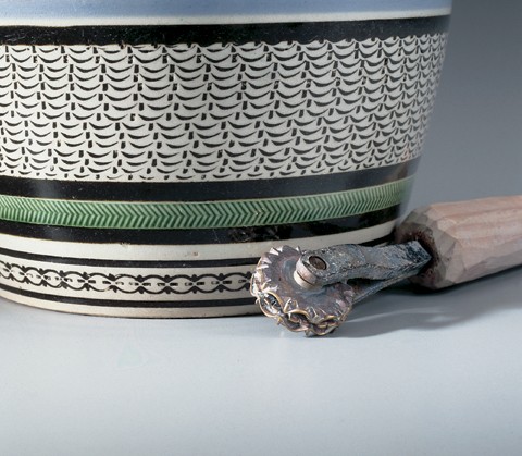
To illustrate the pantographic effect of the cam in relation to the pattern cut on a pot, Don devised this arrangement of an edge cam with a period mug. The white lines on the cam show the reduction of the edge pattern to the final cut. The larger the cam, the more spread out the pattern became, thus increasing the ease of following the pattern. (Collection of Donald Carpentier.)
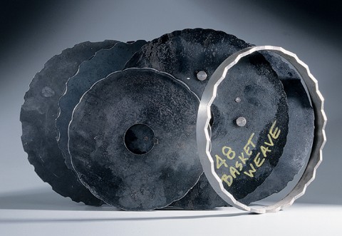
An assortment of end and edge cams, each of which is capable of many patterns depending on the blades chosen.
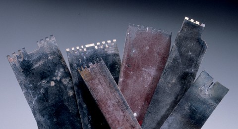
An assortment of cutting blades.
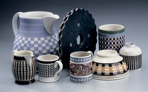
A group of engine-turned vessels having a variety of decorations. (Collection of Donald Carpentier; photo, Gavin Ashworth.) All of these pieces were cut using one or both sides of a checking cam, similar to the one seen in the center of the illustration. Most of the variations were created by changing either the slip colors or the patterns on the ends of the cutting blades.
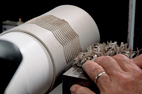
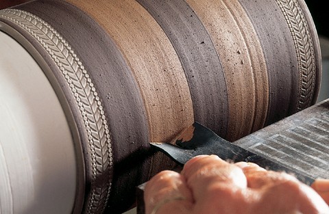
Beginning the process of cutting a pattern into a quart-mug’s surface using the end cam. The pot revolves as the blade gradually begins to cut into the surface.
With the pattern completely cut in, the surface is flooded with colored slip and set aside to dry.
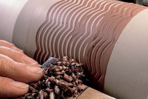
After drying, the excess slip is turned away with a flat blade, exposing both the white body of the pot and the red clay inlay.
Detail of the inlaid slip pattern prior to the biscuit firing.
The completed mug prior to biscuit firing. As these modern pots are intended to be used, non-leaded glazes are applied. Carpentier discovered that lead was an integral component in producing the colors of the glazes. Consequently, he had to develop his own clay sources and color recipes to achieve the look of the original lead-glazed products.
Jug, British, ca. 1820. Pearlware. H. 7 3/4". (Collection of Donald Carpentier; photo, Gavin Ashworth.) A barrel-form jug, slip-banded with black slip-filled rouletted decoration. Rouletted decoration such as this illustrates the imprecise geometric patterns achieved by hand, as opposed to the regular patterns found on engine-turned wares. The use of the end cam seems to have diminished by the 1830s, but edge-cam work continued to the end of the nineteenth century. By the early nineteenth century the much simpler and less expensive dicing lathes were available as stock items. Cams were also available in standard sets, obvious from sherds found on various factory sites. The only known period engine-lathe cams are at the Wedgwood factory in Barlaston, Staffordshire.
Detail of a rouletted inlay in three different patterns, together with a rouletting wheel in one of those patterns (three different roulettes were used). Many factories were too small or too under-capitalized to afford even a dicing lathe, and they had few options available in order to compete. One of those options was to become very creative with the practice of inlaid rouletting. Most factories had a variety of these inexpensive and easily available patterned wheels that could be used in a variety of combinations. The surface of the pot was simply embossed using the roulette and the ornamental depression created was filled with a colored slip. Once the slip had set, the excess was trimmed away on the lathe, leaving an inlaid pattern. Many inlaid designs are similar in design to engine-turned patterns and are incorrectly attributed to engine turning by many dealers and collectors.
Teapot, Staffordshire, ca. 1770. Earthenware. H. 4 1/8". (Courtesy, Skinner’s.) This teapot has typical engine-turned decoration under its colorful glaze, and without close inspection one would assume that it had been cut on such a lathe. In fact, this pot was press-molded. The blocks used to produce the molds in which it was pressed were made from an original master model that was, in fact, cut on an engine lathe. Mold marks run down both the front and rear of the pot and are partially obscured by the handle and spout. This technique was one of the ways that small potteries could compete with larger firms that had expensive engine lathes.
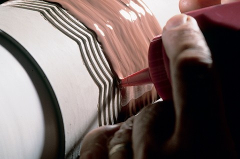
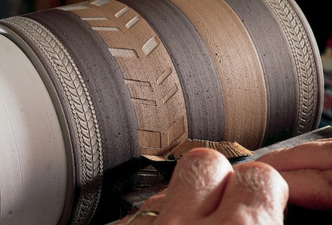
Beginning the process of cutting a pattern with the edge cam through firm slip on the leather-hard body of a quart mug. Because of the need for full circumferential access, the last step before biscuit firing is the application of the
handle. In this pattern, chevrons are an integral part of the design, so a V-shaped rather than flat blade is used. The rouletted patterns near the rim and the foot will be brushed with a concentrated glaze mixture containing copper oxide
The earliest stage of cutting the chevron pattern.
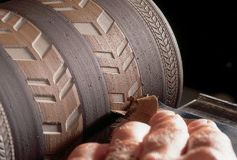
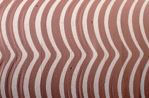
The pattern begins to reveal the body color beneath the slip.
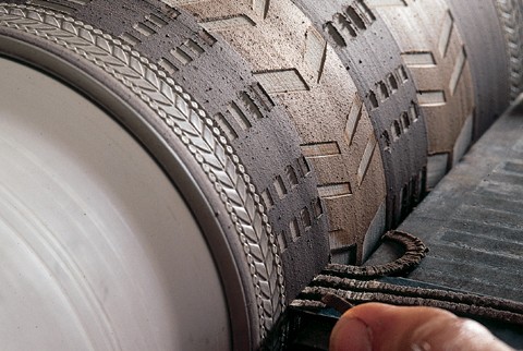
A different blade being used to cut the short dashes through the contrasting slip band.
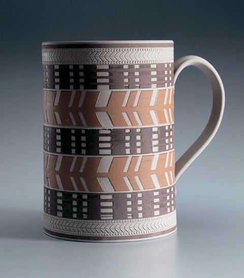
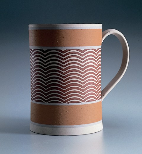
The completed mug prior to biscuit firing.